- Home
- Cable Glands
- Products
- Industrial / General Purpose
- E2U | Industrial Cable Gland
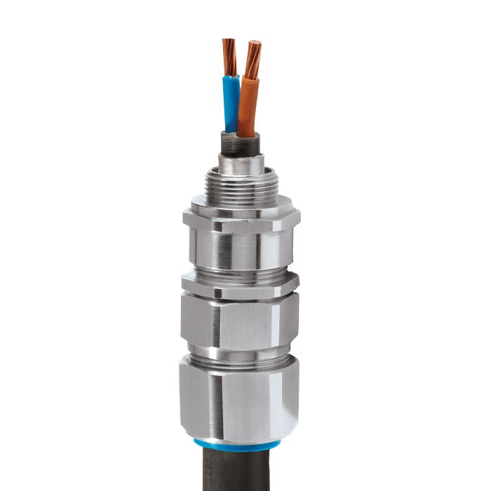
E2U | Industrial Cable Gland For all types of Lead Sheathed Armoured Cables
We'd like to keep in touch
We have some exciting things in the pipeline - if you'd like to be the first to know please enter your email address below.
Double Seal Industrial Cable Gland
• Effectively earths / grounds lead sheathed cables
• Metal-to-metal armour clamping
• Direct & remote installation
• Permanently crimped, low impedance earth termination
• Secure against self-loosening
• Displacement type inner seal
• Controlled outer ‘load retention’ seal
• Unique OSTG prevents overtightening
• Designed to prevent Coldflow
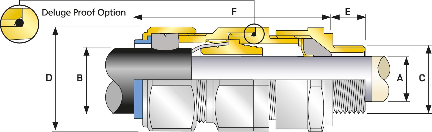
• Deluge protection option
• -60°C to +130°C
• EMC tested
For under / oversized armour wires click here
| Design Specification | BS 6121:Part 1:1989, IEC 62444, EN 62444 |
| Mechanical Classifications * | Impact = Level 8, Retention = Class D |
| Enclosure Protection | IK10 to IEC 62262 (20 joules) Brass & Stainless Steel only |
| Electrical Classifications * | Category B (Category A when used with braid, tape or pliable wire armour cables) |
| GOST R Certificate | POCC.GB.HA46.H00140 |
| Marine Approvals | LRS: 01/00171 (E1), ABS: 16-LD1472056-PDA |
| Ingress Protection Rating ** | IP66 as standard (IP67, IP68 available upon request) |
| Cable Gland Material | Brass, Electroless Nickel Plated Brass, Aluminium |
| Seal Material | CMP Thermoset Rubber |
| Cable Type | Lead Sheathed & Single Wire Armour (LC/SWA), Lead Sheathed & Wire Braid Armour, Lead Sheathed & Steel Tape Armour (LC/STA), Lead Sheathed & Pliable Wire Armour (LC/ PWA), Lead Sheathed & Strip Armour (LC/ASA) |
| Armour Clamping | Reversible Armour Cone & AnyWay Universal Clamping Ring |
| Sealing Technique | CMP Inner Displacement Seal & Unique CMP ‘LRS’ TM Outer Load Retention Seal |
| Sealing Area(s) | Cable Inner Lead Sheath & Outer Sheath |
| Optional Accessories | Locknuts, Earth Tags, Serrated Washers, Entry Thread Seals, Shrouds,Ingress Discs |
| Optional Installation Tools | Spanners |
* Mechanical & Electrical Classifications applied as per IEC 62444 & EN 62444
** Refer to Maintaining a Seal for further information on Ingress Protection Ratings
Certificates


Product Selection Table
Click here to view how to order
| Cable Gland Size | Available Entry Threads 'C' (Alternate Metric Thread Lengths Available) | Cable Lead Sheath Diameter 'A' | Overall Cable Diameter 'B' | Armour Range | Across Flats 'D' | Across Corners 'D' | Protrusion Length 'F' | Combined Ordering Reference (*Brass Metric) | Shroud | Cable Gland Weight (Kgs) |
|||||||||||
| Standard | Option | Grooved Cone (X) | Stepped Cone (W) | ||||||||||||||||||
| Metric | Thread Length (Metric) 'E' | NPT | Thread Length (NPT) 'E' | NPT | Min | Max | Min | Max | Min | Max | Min | Max | Max | Max | Size | Type | Ordering Suffix |
||||
| 20S16 | M20 | 0.39 | ½' | 0.78 | ¾' | 0.12 | 0.31 | 0.24 | 0.52 | 0.01 | 0.04 | 0.03 | 0.05 | 0.94 | 1.04 | 2.85 | 20S16 | E2U | 1RA | PVC04 | 5.64 |
| 20S | M20 | 0.39 | ½' | 0.78 | ¾' | 0.24 | 0.43 | 0.37 | 0.63 | 0.01 | 0.04 | 0.03 | 0.05 | 0.94 | 1.04 | 2.76 | 20S | E2U | 1RA | PVC04 | 5.29 |
| 20 | M20 | 0.39 | ½' | 0.78 | ¾' | 0.26 | 0.53 | 0.49 | 0.82 | 0.02 | 0.04 | 0.03 | 0.05 | 1.20 | 1.32 | 2.87 | 20 | E2U | 1RA | PVC06 | 7.41 |
| 25S | M25 | 0.39 | ¾' | 0.80 | 1' | 0.44 | 0.76 | 0.55 | 0.87 | 0.02 | 0.05 | 0.05 | 0.06 | 1.48 | 1.63 | 3.50 | 25S | E2U | 1RA | PVC09 | 11.64 |
| 25 | M25 | 0.39 | ¾' | 0.80 | 1' | 0.44 | 0.76 | 0.72 | 1.03 | 0.02 | 0.05 | 0.05 | 0.06 | 1.48 | 1.63 | 3.50 | 25 | E2U | 1RA | PVC09 | 11.64 |
| 32 | M32 | 0.39 | 1' | 0.98 | 1 ¼' | 0.67 | 1.00 | 0.93 | 1.33 | 0.02 | 0.05 | 0.06 | 0.08 | 1.81 | 1.99 | 3.39 | 32 | E2U | 1RA | PVC11 | 15.17 |
| 40 | M40 | 0.59 | 1 ¼' | 1.01 | 1 ½' | 0.87 | 1.23 | 1.10 | 1.59 | 0.02 | 0.06 | 0.06 | 0.08 | 2.17 | 2.38 | 3.54 | 40 | E2U | 1RA | PVC15 | 21.87 |
| 50S | M50 | 0.59 | 1 ½' | 1.03 | 2' | 1.16 | 1.46 | 1.39 | 1.84 | 0.02 | 0.06 | 0.08 | 0.10 | 2.36 | 2.60 | 3.58 | 50S | E2U | 1RA | PVC18 | 26.46 |
| 50 | M50 | 0.59 | 2' | 1.06 | 2 ½' | 1.40 | 1.68 | 1.59 | 2.09 | 0.02 | 0.06 | 0.08 | 0.10 | 2.76 | 3.04 | 3.74 | 50 | E2U | 1RA | PVC21 | 33.86 |
| 63S | M63 | 0.59 | 2' | 1.06 | 2 ½' | 1.58 | 1.91 | 1.80 | 2.34 | 0.02 | 0.06 | 0.08 | 0.10 | 2.95 | 3.25 | 4.02 | 63S | E2U | 1RA | PVC23 | 47.62 |
| 63 | M63 | 0.59 | 2 ½' | 1.57 | 3' | 1.86 | 2.13 | 2.15 | 2.59 | 0.02 | 0.06 | 0.08 | 0.10 | 3.15 | 3.46 | 4.09 | 63 | E2U | 1RA | PVC25 | 47.62 |
| 75S | M75 | 0.59 | 2 ½' | 1.57 | 3' | 2.08 | 2.37 | 2.32 | 2.83 | 0.02 | 0.06 | 0.08 | 0.10 | 3.54 | 3.90 | 4.53 | 75S | E2U | 1RA | PVC28 | 74.78 |
| 75 | M75 | 0.59 | 3' | 1.63 | 3 ½' | 2.33 | 2.57 | 2.63 | 3.09 | 0.02 | 0.06 | 0.10 | 0.12 | 3.94 | 4.33 | 4.61 | 75 | E2U | 1RA | PVC30 | 85.72 |
| 90 | M90 | 0.94 | 3 ½' | 1.69 | 4' | 2.62 | 3.04 | 3.00 | 3.56 | 0.03 | 0.06 | 0.12 | 0.16 | 4.50 | 4.94 | 5.79 | 90 | E2U | 1RA | PVC32 | 149.21 |
| 100 | M100 | 0.94 | 4' | 1.73 | 5' | 2.99 | 3.47 | 3.39 | 3.99 | 0.03 | 0.06 | 0.12 | 0.16 | 4.84 | 5.33 | 5.51 | 100 | E2U | 1RA | LSF33 | 157.67 |
| 115 | M115 | 0.94 | 4' | 1.73 | 5' | 3.39 | 3.70 | 4.00 | 4.34 | 0.03 | 0.06 | 0.12 | 0.16 | 5.25 | 5.78 | 6.38 | 115 | E2U | 1RA | LSF34 | 219.05 |
| 130 | M130 | 0.94 | 5' | 1.84 | 6' | 3.82 | 4.33 | 4.34 | 4.85 | 0.03 | 0.06 | 0.12 | 0.16 | 6.00 | 6.60 | 6.85 | 130 | E2U | 1RA | LSF35 | 294.89 |
| Dimensions displayed in inches unless otherwise stated | |||||||||||||||||||||
| Cable Gland Size | Available Entry Threads 'C' (Alternate Metric Thread Lengths Available) | Cable Lead Sheath Diameter 'A' | Overall Cable Diameter 'B' | Armour Range | Across Flats 'D' | Across Corners 'D' | Protrusion Length 'F' | Combined Ordering Reference (*Brass Metric) | Shroud | Cable Gland Weight (Kgs) |
|||||||||||
| Standard | Option | Grooved Cone (X) | Stepped Cone (W) | ||||||||||||||||||
| Metric | Thread Length (Metric) 'E' | NPT | Thread Length (NPT) 'E' | NPT | Min | Max | Min | Max | Min | Max | Min | Max | Max | Max | Size | Type | Ordering Suffix |
||||
| 20S16 | M20 | 10.0 | ½' | 19.9 | ¾' | 3.1 | 7.8 | 6.1 | 13.1 | 0.3 | 1.0 | 0.8 | 1.25 | 24.0 | 26.4 | 72.5 | 20S16 | E2U | 1RA | PVC04 | 0.16 |
| 20S | M20 | 10.0 | ½' | 19.9 | ¾' | 6.1 | 11.0 | 9.5 | 15.9 | 0.3 | 1.0 | 0.8 | 1.25 | 24.0 | 26.4 | 70.0 | 20S | E2U | 1RA | PVC04 | 0.15 |
| 20 | M20 | 10.0 | ½' | 19.9 | ¾' | 6.5 | 13.4 | 12.5 | 20.9 | 0.4 | 1.0 | 0.8 | 1.25 | 30.5 | 33.6 | 73.0 | 20 | E2U | 1RA | PVC06 | 0.21 |
| 25S | M25 | 10.0 | ¾' | 20.2 | 1' | 11.1 | 19.3 | 14.0 | 22.0 | 0.4 | 1.2 | 1.25 | 1.6 | 37.5 | 41.3 | 89.0 | 25S | E2U | 1RA | PVC09 | 0.33 |
| 25 | M25 | 10.0 | ¾' | 20.2 | 1' | 11.1 | 19.3 | 18.2 | 26.2 | 0.4 | 1.2 | 1.25 | 1.6 | 37.5 | 41.3 | 89.0 | 25 | E2U | 1RA | PVC09 | 0.33 |
| 32 | M32 | 10.0 | 1' | 25.0 | 1 ¼' | 17.0 | 25.5 | 23.7 | 33.9 | 0.4 | 1.2 | 1.6 | 2.0 | 46.0 | 50.6 | 86.0 | 32 | E2U | 1RA | PVC11 | 0.43 |
| 40 | M40 | 15.0 | 1 ¼' | 25.6 | 1 ½' | 22.0 | 31.2 | 27.9 | 40.4 | 0.4 | 1.6 | 1.6 | 2.0 | 55.0 | 60.5 | 90.0 | 40 | E2U | 1RA | PVC15 | 0.62 |
| 50S | M50 | 15.0 | 1 ½' | 26.1 | 2' | 29.5 | 37.2 | 35.2 | 46.7 | 0.4 | 1.6 | 2.0 | 2.5 | 60.0 | 66.0 | 91.0 | 50S | E2U | 1RA | PVC18 | 0.75 |
| 50 | M50 | 15.0 | 2' | 26.9 | 2 ½' | 35.6 | 42.6 | 40.4 | 53.0 | 0.6 | 1.6 | 2.0 | 2.5 | 70.1 | 77.1 | 95.0 | 50 | E2U | 1RA | PVC21 | 0.96 |
| 63S | M63 | 15.0 | 2' | 26.9 | 2 ½' | 40.1 | 48.5 | 45.6 | 59.4 | 0.6 | 1.6 | 2.0 | 2.5 | 75.0 | 82.5 | 102.0 | 63S | E2U | 1RA | PVC23 | 1.35 |
| 63 | M63 | 15.0 | 2 ½' | 39.9 | 3' | 47.2 | 54.2 | 54.6 | 65.8 | 0.6 | 1.6 | 2.0 | 2.5 | 80.0 | 88.0 | 104.0 | 63 | E2U | 1RA | PVC25 | 1.35 |
| 75S | M75 | 15.0 | 2 ½' | 39.9 | 3' | 52.8 | 60.2 | 59.0 | 72.0 | 0.6 | 1.6 | 2.0 | 2.5 | 90.0 | 99.0 | 115.0 | 75S | E2U | 1RA | PVC28 | 2.12 |
| 75 | M75 | 15.0 | 3' | 41.5 | 3 ½' | 59.1 | 65.2 | 66.7 | 78.4 | 0.6 | 1.6 | 2.5 | 3.0 | 100.0 | 110.0 | 117.0 | 75 | E2U | 1RA | PVC30 | 2.43 |
| 90 | M90 | 24.0 | 3 ½' | 42.8 | 4' | 66.6 | 77.1 | 76.2 | 90.3 | 0.8 | 1.6 | 3.15 | 4.0 | 114.3 | 125.4 | 147.0 | 90 | E2U | 1RA | PVC32 | 4.23 |
| 100 | M100 | 24.0 | 4' | 44.0 | 5' | 76.0 | 88.1 | 86.1 | 101.4 | 0.8 | 1.6 | 3.15 | 4.0 | 123.0 | 135.3 | 140.0 | 100 | E2U | 1RA | LSF33 | 4.47 |
| 115 | M115 | 24.0 | 4' | 44.0 | 5' | 86.0 | 94.1 | 101.5 | 110.2 | 0.8 | 1.6 | 3.15 | 4.0 | 133.4 | 146.7 | 162.0 | 115 | E2U | 1RA | LSF34 | 6.21 |
| 130 | M130 | 24.0 | 5' | 46.8 | 6' | 97.0 | 110.1 | 110.2 | 123.2 | 0.8 | 1.6 | 3.15 | 4.0 | 152.4 | 167.6 | 174.0 | 130 | E2U | 1RA | LSF35 | 8.36 |
| Dimensions displayed in millimeters unless otherwise stated | |||||||||||||||||||||
Lead Covered / Lead Sheathed Cables
In addition to the standard requirements for SWA cables, there is a set of special guidelines for lead covered cables intended for direct burial in the ground of hydrocarbons processing and refinery sites. These guidelines were introduced in the UK by the Oil Companies Material Association (OCMA) and responsibility for these were subsequently transferred to EEMUA, the Engineering Equipment and Material Users Association.
Read moreVisit our Knowledge Base for technical expertise and advice, gathered over CMP's 60+ years' experience in the art of terminating cable glands.
Log in now