- Home
- Cable Glands
- Products
- Industrial / General Purpose
- C2KGP | Industrial Cable Gland
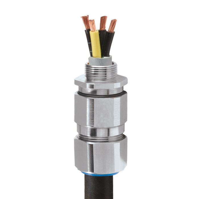
C2KGP | Industrial Cable Gland For all types of Armoured Cables
We'd like to keep in touch
We have some exciting things in the pipeline - if you'd like to be the first to know please enter your email address below.
Single Seal Industrial Cable Gland
• High quality durable materials
• Robust, heavy duty design
• Metal-to-metal armour clamping
• Direct & remote installation
• Controlled outer ‘load retention’ seal
• Unique OSTG prevents overtightening
• Integral protected deluge seal
• -60°C to +130°C
• Superior EMC performance
Note: † Grooved Cone (X) is predominantly used for Wire Braid (e.g. GSWB, TCWB), Steel Tape Armour (STA, DSTA) and Aluminium Strip Armour (ASA) but is also suitable for Single Wire Armour (SWA), Aluminium Wire Armour (AWA) and Pliable Wire Armour (PWA) if the range is outside that of the Stepped Cone (W).
Note: Grooved Cone (X) dimensions shown in the Cable Gland Selection Table below are for a double wire strand of braid armour cables. Tapes can also be doubled over. For cables that have only a single layer of armour such as SWA the clamping range should be used as shown in the table below.
Stepped (W) Cone is suitable for Single Wire Armour (SWA), or Aluminium Wire Armour (AWA) cables.
For under / oversized armour wires click here
| Design Specification | BS 6121:Part 1:1989, IEC 62444, EN 62444 |
| Mechanical Classifications * | Impact = Level 8, Retention = Class D |
| Enclosure Protection | IK10 to IEC 62262 (20 joules) Brass & Stainless Steel only |
| Electrical Classifications * | Category B (Category A when used with braid, tape or pliable wire armour cables) |
| GOST R Certificate | POCC.GB.HA46.H00140 |
| Marine Approvals | LRS: 01/00171 |
| Ingress Protection Rating ** | IP66, IP67 & IP68 |
| Deluge Protection Compliance | DTS01 : 91 |
| Cable Gland Material | Brass, Electroless Nickel Plated Brass, Stainless Steel, Aluminium |
| Seal Material | CMP Thermoset Rubber |
| Cable Type | Single Wire Armour (SWA), Aluminium Wire Armour (AWA), Steel Tape Armour (STA), Aluminium Strip Armour (ASA), Wire Braid Armour, Screened Flexible (EMC) Wire Braid (e.g. CY / SY), Pliable Wire Armour (PWA) |
| Armour Clamping | Reversible Armour Cone & AnyWay Universal Clamping Ring |
| Sealing Technique | Unique CMP ‘LRS’ Outer Seal (Load Retention Seal) |
| Sealing Area(s) | Cable Outer Sheath |
| Optional Accessories | Locknuts, Earth Tags, Serrated Washers, Entry Thread Seals, Shrouds,Ingress Discs |
| Optional Installation Tools | Spanners, Armour Former Tool |
Note : * Mechanical & Electrical Classifications applied as per IEC 62444 & EN 62444
** Refer to Maintaining a Seal for further information on Ingress Protection Ratings
Certificates


Product Selection Table
Click here to view how to order
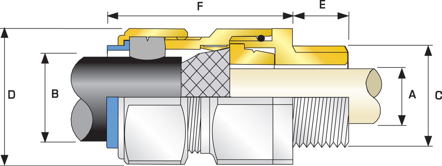
| Cable Gland Size | Available Entry Threads 'C' (Alternate Metric Thread Lengths Available) | Cable Bedding Diameter 'A' | Overall Cable Diameter 'B' | Armour Range | Across Flats 'D' | Across Corners 'D' | Protrusion Length 'F' | Combined Ordering Reference (*Brass Metric) | Shroud | Cable Gland Weight (Ozs) |
|||||||
| Grooved Cone (X) | Stepped Cone (W) | ||||||||||||||||
| Metric | Thread Length (Metric) 'E' | Max | Max | Max | Min | Max | Max | Max | Max | Max | Size | Type | Ordering Suffix |
||||
| 20S16 | M20 | 0.39 | 0.34 | 0.24 | 0.52 | 0.01 | 0.04 | 0.03 | 0.05 | 1.20 | 1.32 | 2.56 | 20S16 | C2KGP | 1RA | PVC06 | 8.11 |
| 20S | M20 | 0.39 | 0.46 | 0.37 | 0.63 | 0.01 | 0.04 | 0.03 | 0.05 | 1.20 | 1.32 | 2.44 | 20S | C2KGP | 1RA | PVC06 | 7.76 |
| 20 | M20 | 0.39 | 0.55 | 0.49 | 0.82 | 0.02 | 0.04 | 0.03 | 0.05 | 1.20 | 1.32 | 2.48 | 20 | C2KGP | 1RA | PVC06 | 7.76 |
| 25S | M25 | 0.39 | 0.79 | 0.55 | 0.87 | 0.02 | 0.05 | 0.05 | 0.06 | 1.48 | 1.63 | 2.74 | 25S | C2KGP | 1RA | PVC09 | 12.35 |
| 25 | M25 | 0.39 | 0.79 | 0.72 | 1.03 | 0.02 | 0.05 | 0.05 | 0.06 | 1.48 | 1.63 | 2.74 | 25 | C2KGP | 1RA | PVC09 | 12.35 |
| 32 | M32 | 0.39 | 1.04 | 0.93 | 1.33 | 0.02 | 0.05 | 0.06 | 0.08 | 1.81 | 1.99 | 2.95 | 32 | C2KGP | 1RA | PVC11 | 19.40 |
| 40 | M40 | 0.59 | 1.27 | 1.10 | 1.59 | 0.02 | 0.06 | 0.06 | 0.08 | 2.17 | 2.38 | 2.95 | 40 | C2KGP | 1RA | PVC15 | 26.46 |
| 50S | M50 | 0.59 | 1.50 | 1.39 | 1.84 | 0.02 | 0.06 | 0.08 | 0.10 | 2.36 | 2.60 | 3.03 | 50S | C2KGP | 1RA | PVC18 | 30.34 |
| 50 | M50 | 0.59 | 1.74 | 1.59 | 2.09 | 0.02 | 0.06 | 0.08 | 0.10 | 2.76 | 3.04 | 3.03 | 50 | C2KGP | 1RA | PVC21 | 39.86 |
| 63S | M63 | 0.59 | 1.97 | 1.80 | 2.34 | 0.02 | 0.06 | 0.08 | 0.10 | 2.95 | 3.25 | 3.15 | 63S | C2KGP | 1RA | PVC23 | 46.91 |
| 63 | M63 | 0.59 | 2.20 | 2.15 | 2.59 | 0.02 | 0.06 | 0.08 | 0.10 | 3.15 | 3.46 | 3.15 | 63 | C2KGP | 1RA | PVC25 | 47.27 |
| 75S | M75 | 0.59 | 2.44 | 2.32 | 2.83 | 0.02 | 0.06 | 0.08 | 0.10 | 3.54 | 3.90 | 3.43 | 75S | C2KGP | 1RA | PVC28 | 71.25 |
| 75 | M75 | 0.59 | 2.68 | 2.63 | 3.09 | 0.02 | 0.06 | 0.10 | 0.12 | 3.94 | 3.94 | 3.46 | 75 | C2KGP | 1RA | PVC30 | 87.48 |
| 90 | M90 | 0.94 | 3.15 | 3.00 | 3.56 | 0.03 | 0.06 | 0.12 | 0.16 | 4.53 | 4.53 | 4.02 | 90 | C2KGP | 1RA | PVC32 | 124.16 |
| 100 | M100 | 0.94 | 3.58 | 3.39 | 3.99 | 0.03 | 0.06 | 0.12 | 0.16 | 5.00 | 5.00 | 4.49 | 100 | C2KGP | 1RA | LSF33 | 161.20 |
| 115 | M115 | 0.94 | 3.86 | 4.00 | 4.34 | 0.03 | 0.06 | 0.12 | 0.16 | 5.25 | 5.25 | 4.49 | 115 | C2KGP | 1RA | LSF34 | 229.28 |
| 130 | M130 | 0.94 | 4.53 | 4.34 | 4.85 | 0.03 | 0.06 | 0.12 | 0.16 | 6.00 | 6.00 | 4.49 | 130 | C2KGP | 1RA | LSF35 | 299.83 |
| Dimensions displayed in inches unless otherwise stated | |||||||||||||||||
| Cable Gland Size | Available Entry Threads 'C' (Alternate Metric Thread Lengths Available) | Cable Bedding Diameter 'A' | Overall Cable Diameter 'B' | Armour Range | Across Flats 'D' | Across Corners 'D' | Protrusion Length 'F' | Combined Ordering Reference (*Brass Metric) | Shroud | Cable Gland Weight (Kgs) |
|||||||
| Grooved Cone (X) | Stepped Cone (W) | ||||||||||||||||
| Metric | Thread Length (Metric) 'E' | Max | Max | Max | Min | Max | Max | Max | Max | Max | Size | Type | Ordering Suffix |
||||
| 20S16 | M20 | 10.0 | 8.7 | 6.1 | 13.1 | 0.3 | 1.0 | 0.8 | 1.25 | 30.5 | 33.6 | 65.0 | 20S16 | C2KGP | 1RA | PVC06 | 0.23 |
| 20S | M20 | 10.0 | 11.7 | 9.5 | 15.9 | 0.3 | 1.0 | 0.8 | 1.25 | 30.5 | 33.6 | 62.0 | 20S | C2KGP | 1RA | PVC06 | 0.22 |
| 20 | M20 | 10.0 | 14.0 | 12.5 | 20.9 | 0.4 | 1.0 | 0.8 | 1.25 | 30.5 | 33.6 | 63.0 | 20 | C2KGP | 1RA | PVC06 | 0.22 |
| 25S | M25 | 10.0 | 20.0 | 14.0 | 22.0 | 0.4 | 1.2 | 1.25 | 1.6 | 37.5 | 41.3 | 69.5 | 25S | C2KGP | 1RA | PVC09 | 0.35 |
| 25 | M25 | 10.0 | 20.0 | 18.2 | 26.2 | 0.4 | 1.2 | 1.25 | 1.6 | 37.5 | 41.3 | 69.5 | 25 | C2KGP | 1RA | PVC09 | 0.35 |
| 32 | M32 | 10.0 | 26.3 | 23.7 | 33.9 | 0.4 | 1.2 | 1.6 | 2.0 | 46.0 | 50.6 | 75.0 | 32 | C2KGP | 1RA | PVC11 | 0.55 |
| 40 | M40 | 15.0 | 32.2 | 27.9 | 40.4 | 0.4 | 1.6 | 1.6 | 2.0 | 55.0 | 60.5 | 75.0 | 40 | C2KGP | 1RA | PVC15 | 0.75 |
| 50S | M50 | 15.0 | 38.2 | 35.2 | 46.7 | 0.4 | 1.6 | 2.0 | 2.5 | 60.0 | 66.0 | 77.0 | 50S | C2KGP | 1RA | PVC18 | 0.86 |
| 50 | M50 | 15.0 | 44.1 | 40.4 | 53.0 | 0.6 | 1.6 | 2.0 | 2.5 | 70.1 | 77.1 | 77.0 | 50 | C2KGP | 1RA | PVC21 | 1.13 |
| 63S | M63 | 15.0 | 50.0 | 45.6 | 59.4 | 0.6 | 1.6 | 2.0 | 2.5 | 75.0 | 82.5 | 80.0 | 63S | C2KGP | 1RA | PVC23 | 1.33 |
| 63 | M63 | 15.0 | 56.0 | 54.6 | 65.8 | 0.6 | 1.6 | 2.0 | 2.5 | 80.0 | 88.0 | 80.0 | 63 | C2KGP | 1RA | PVC25 | 1.34 |
| 75S | M75 | 15.0 | 62.0 | 59.0 | 72.0 | 0.6 | 1.6 | 2.0 | 2.5 | 90.0 | 99.0 | 87.0 | 75S | C2KGP | 1RA | PVC28 | 2.02 |
| 75 | M75 | 15.0 | 68.0 | 66.7 | 78.4 | 0.6 | 1.6 | 2.5 | 3.0 | 100.0 | 100.0 | 88.0 | 75 | C2KGP | 1RA | PVC30 | 2.48 |
| 90 | M90 | 24.0 | 80.0 | 76.2 | 90.3 | 0.8 | 1.6 | 3.15 | 4.0 | 115.0 | 126.5 | 102.0 | 90 | C2KGP | 1RA | PVC32 | 3.52 |
| 100 | M100 | 24.0 | 91.0 | 86.1 | 101.4 | 0.8 | 1.6 | 3.15 | 4.0 | 127.0 | 139.7 | 114.0 | 114 | C2KGP | 1RA | LSF33 | 4.57 |
| 115 | M115 | 24.0 | 98.0 | 101.5 | 110.2 | 0.8 | 1.6 | 3.15 | 4.0 | 133.4 | 133.4 | 146.7 | 114 | C2KGP | 1RA | LSF34 | 6.50 |
| 130 | M130 | 24.0 | 115.0 | 110.2 | 123.2 | 0.8 | 1.6 | 3.15 | 4.0 | 152.4 | 152.4 | 167.6 | 114 | C2KGP | 1RA | LSF35 | 8.50 |
| Dimensions displayed in millimeters unless otherwise stated | |||||||||||||||||
BS 6121-1:1989 vs IEC 62444 / EN 62444
Whilst new standards such as IEC 62444 and EN 62444 have more recently been introduced, which CMP Products fully complies with, BS 6121-1:1989 still remains a very important benchmark for users and manufacturers around the world, due mainly to the fact that it is a more onerous construction standard than others published. This will therefore be especially relevant where a national cable gland standard isn’t available. The tables below show the maximum cable entry bore size and tolerances permitted through the range of BS 6121-1:1989 cable gland sizes.
Read moreProtection by Enclosure Against Mechanical Impact
It is critically important that enclosures afford a level of mechanical protection relevant to the area of installation that provides optimum electrical and operational safety. The international standard IEC 62262 covering ‘Degrees of protection provided by enclosures for electrical equipment against external mechanical impacts (IK Code)’ outlines the requirements for testing and rating of enclosures of different materials, so that careful selection to suit the application can be achieved.
Read moreCMP Ingress Protection Testing
Some CMP cable gland types have been tested to IP66, whilst other types have been tested to IP66, IP67 & IP68, to an equivalent depth of up to 60 metres for a duration of two weeks. For manufacturers to claim an IP68 protection level it is important that they include both the depth of water and time duration of the test conducted; otherwise the rating would be incomplete and meaningless.
Read moreVisit our Knowledge Base for technical expertise and advice, gathered over CMP's 60+ years' experience in the art of terminating cable glands.
Sign up now