- Home
- Cable Glands
- Products
- Explosive Atmosphere
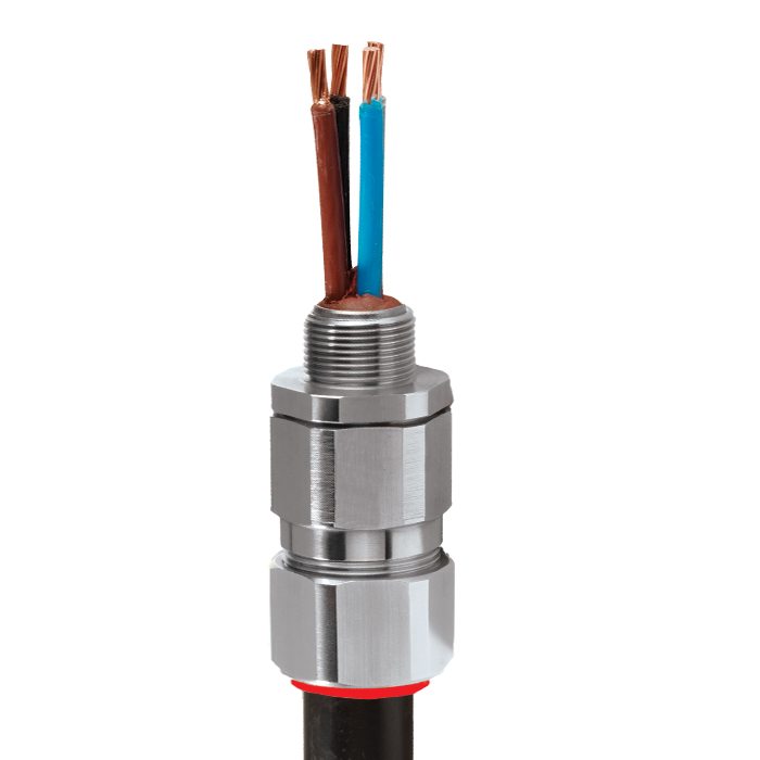
- PX2KX | Ex eb, Ex db, Ex nR & Ex ta | Explosive Atmosphere Barrier Cable Gland
- Ex nR
- Ex ta
PX2KX | Ex eb, Ex db, Ex nR & Ex ta | Explosive Atmosphere Barrier Cable Gland For all types of Braid & Tape Armoured Cables
We'd like to keep in touch
We have some exciting things in the pipeline - if you'd like to be the first to know please enter your email address below.
Globally Approved, Explosive Atmosphere Barrier Cable Gland
• Metal-to-metal armour clamping
• Direct & remote installation
• Compound barrier type flameproof seal
• Controlled outer ‘load retention’ seal
• Unique OSTG prevents overtightening
• Integral protected deluge seal
• -60°C to +85°C
• Class I Zone 1, 21 and Zone 2, 22 Class I Division 1 & 2 ABCD
• Globally marked, IECEx, ATEX, UL & cCSAus
• Superior EMC performance
• Compound barrier seals around internal cable cores after removing any inner cable sheath/bedding; completely eliminating any risk of coldflow
† Grooved Cone (X) is predominantly used for Wire Braid (e.g. GSWB, TCWB), Steel Tape Armour (STA, DSTA) and Aluminium Strip Armour (ASA) but is also suitable for Single Wire Armour (SWA), Aluminium Wire Armour (AWA) and Pliable Wire Armour (PWA) if the range is outside that of the Stepped Cone (W).
Note: Grooved Cone (X) dimensions shown in the Cable Gland Selection Table below are for a double wire strand of braid armour cables. Tapes can also be doubled over. For cables that have only a single layer of armour such as SWA the clamping range should be used as shown in the table below.
| Design Specification | BS 6121:Part 1:1989, IEC 62444, EN 62444 |
| Mechanical Classifications * | Impact = Level 8, Retention = Class B |
| Enclosure Protection | IK10 to IEC 62262 (20 joules) Brass & Stainless Steel only |
| Electrical Classifications * | Category B (Category A when used with braid, tape or pliable wire armour cables) |
| ATEX Certificate | CML 18ATEX1325X, CML 18ATEX4317X |
| UKEX Certificate | CML 21UKEX1214X, CML 21UKEX4215X |
| Code of Protection | II 2G, II 1D, Ex db IIC Gb, Ex eb IIC Gb, Ex ta IIIC Da, II 3G Ex nR IIC Gc, IM2 Ex db I Mb, Ex eb I Mb |
| Compliance Standards | EN 60079-0,1,7,15,31 |
| IECEx Certificate | IECEx CML 18.0182X |
| Code of Protection | Ex db IIC Gb, Ex eb IIC Gb, Ex nR IIC Gc, Ex ta IIIC Da, Ex db I Mb, Ex eb I Mb |
| Compliance Standards | IEC 60079-0,1,7,15,31 |
| cCSAus Certificate (20s16 - 100) | 2288626 |
| CSAus Code of Protection*** | Class I, Div. 1, 2 Groups A, B, C and D; Class II, Div. 1, 2 Groups E, F and G; Class III, Div. 1, 2; Type 4X: Oil Resistant II: Class I, Zone 1 AEx d IIC Gb, AEx e IIC Gb, Class I, Zone 2 AEx nR IIC Gc, Class I, Zone 20 AEx ta IIIC Da |
| CSAus Code of Protection*** | Class I, Div. 1, 2 Groups A, B, C and D; Class II, Div. 1, 2 Groups E, F and G; Class III, Div. 1, 2; Type 4X: Oil Resistant II: Ex d IIC Gb, Ex e IIC Gb, Ex nR IIC Gc, Ex ta IIIC Da |
| Compliance Standards | CAN/CSA-C22.2 No 0,18,25,30,94,174, CAN/CSA-E60079-0,1,7,15,31 CAN/CSA-E61241-1-1 Part 1-1, ANSI/UL 514B Ed 5, ANSI/UL 50 Ed 11, ANSI/UL 2225 Ed 4, UL60079 |
| UL Certificate (20s16 - 100) | E201187 -19990428 |
| Code of Protection | Class I Div 1,2, Groups A,B,C,D, Class II Div 1,2, Groups E,F,G |
| Compliance Standards | UL 2225, CSA C22.2 No 174 |
| EAC Certificate | EAC KZ 7100841.01.01.07871 |
| UkrSEPRO | CU 19.0371X |
| KCs Certificate | 14-GA4BO-0252X |
| CCOE / PESO (India) Certificate | Ex d: P548696, Ex e: P533772 Ex nR: P548695 |
| CCC Certificate | 2020322313003190 |
| INMETRO Certificate | TÜV 12.2073X |
| RETIE Certificate | EL-CS-220061 |
| Marine Approvals | LRS: LR22320255TA, DNV: TAE00000Y, ABS: 25-0285992-PDA - Hazardous Cable Glands, BV: 43180/A1BV |
| Ingress Protection Rating ** | IP66, IP67 & IP68 |
| Deluge Protection Compliance | DTS01 : 91 |
| Cable Gland Material | Electroless Nickel Plated Brass, Brass, Stainless Steel, Aluminium |
| Seal Material | CMP SOLO LSF Halogen Free Thermoset Elastomer / Epoxy Barrier Compound |
| Cable Type | Screened Flexible (EMC) Wire Braid (e.g. CY / SY), Pliable Wire Armour (PWA), Steel Tape Armour (STA), Wire Braid Armour (e.g. SWB), Aluminium Strip Armour (ASA), Armoured & Jacketed*** |
| Armour Clamping | Detachable Compound Tube / Cone & AnyWay Universal Clamping Ring |
| Sealing Area(s) | Inner Compound Barrier & Outer Sheath |
| Sealing Technique | Unique CMP ‘LRS’ Outer Seal (Load Retention Seal) |
| Optional Accessories | Locknuts, Earth Tags, Serrated Washers, Entry Thread Seals, Shrouds,Ingress Discs |
| Optional Installation Tools | Spanners |
| SANS | MS-XPL21962 21.0305X |
| ECAS Certificate | 24-03-106290/E24-03-110155/NB0007 |
* Mechanical & Electrical Classifications applied as per IEC 62444 & EN 62444
** When CMP installation accessories are used. Refer to Maintaining a Seal for further information.
***Where the cable is permitted by code (NEC and/or CEC)
*** IP68 tested to a minimum depth of 30 metres for 12 hours, alternate depths / durations can be provided upon request
Certificates


Product Selection Table
Click here to view how to order
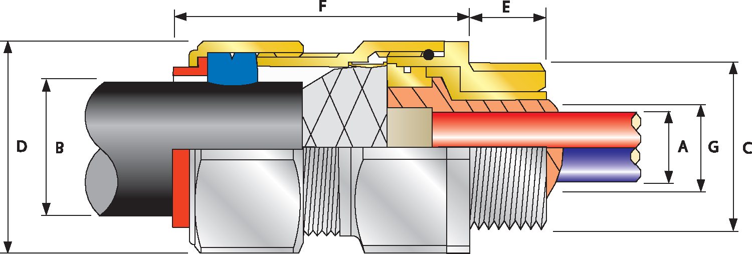
| Combined Ordering Reference (*Nickel Plated Brass NPT) | Available Entry Threads 'C' (Alternative Metric Thread Lengths Available) | Number of Cores | Diameter Over Conductors 'A' | Cable Bedding Diameter 'G' | Overall Cable Diameter 'B' | Armor Range Grooved Cone (X) | Across Flats 'D' | Across Corners 'D' | Protrusion Length 'F' | Shroud | Cable Gland Weight (oz) |
|||||||
| Size | Type | Ordering Suffix | NPT | NPT (Option) | Metric (Option) | Thread Length (NPT) 'E' | Min | Max | ||||||||||
| 20S16 | PX2KX | 1RA531 | ½" | ¾" | M20 | 0.78 | 21 | 0.46 | 0.46 | 0.24 | 0.52 | 0.01 | 0.04 | 1.20 | 1.32 | 2.44 | PVC06 | 8.47 |
| 20S | PX2KX | 1RA531 | ½" | ¾" | M20 | 0.78 | 21 | 0.46 | 0.46 | 0.37 | 0.63 | 0.01 | 0.04 | 1.20 | 1.32 | 2.44 | PVC06 | 8.11 |
| 20 | PX2KX | 1RA531 | ½" | ¾" | M20 | 0.78 | 21 | 0.50 | 0.51 | 0.49 | 0.82 | 0.02 | 0.04 | 1.20 | 1.32 | 2.48 | PVC06 | 8.47 |
| 25S | PX2KX | 1RA532 | ¾" | 1" | M25 | 0.80 | 30 | 0.69 | 0.70 | 0.55 | 0.87 | 0.02 | 0.05 | 1.48 | 1.62 | 2.74 | PVC09 | 13.05 |
| 25 | PX2KX | 1RA532 | ¾" | 1" | M25 | 0.80 | 30 | 0.69 | 0.70 | 0.72 | 1.03 | 0.02 | 0.05 | 1.48 | 1.62 | 2.74 | PVC09 | 13.05 |
| 32 | PX2KX | 1RA533 | 1" | 1 ¼" | M32 | 0.98 | 38 | 0.93 | 0.94 | 0.93 | 1.34 | 0.02 | 0.05 | 1.81 | 1.99 | 2.95 | PVC11 | 20.11 |
| 40 | PX2KX | 1RA534 | 1 ¼" | 1 ½" | M40 | 1.01 | 59 | 1.18 | 1.19 | 1.10 | 1.59 | 0.02 | 0.06 | 2.17 | 2.38 | 2.95 | PVC15 | 28.22 |
| 50S | PX2KX | 1RA535 | 1 ½" | 2" | M50 | 1.03 | 89 | 1.44 | 1.45 | 1.39 | 1.84 | 0.02 | 0.06 | 2.36 | 2.60 | 3.03 | PVC18 | 31.75 |
| 50 | PX2KX | 1RA536 | 2" | 2 ½" | M50 | 1.06 | 115 | 1.61 | 1.63 | 1.59 | 2.09 | 0.02 | 0.06 | 2.76 | 3.04 | 3.03 | PVC21 | 41.98 |
| 63S | PX2KX | 1RA536 | 2" | 2 ½" | M63 | 1.06 | 115 | 1.89 | 1.88 | 1.80 | 2.34 | 0.02 | 0.06 | 2.95 | 3.25 | 3.14 | PVC23 | 49.03 |
| 63 | PX2KX | 1RA537 | 2 ½" | 3" | M63 | 1.57 | 115 | 2.11 | 2.13 | 2.15 | 2.59 | 0.02 | 0.06 | 3.15 | 3.46 | 3.16 | PVC25 | 49.74 |
| 75S | PX2KX | 1RA537 | 2 ½" | 3" | M75 | 1.57 | 140 | 2.36 | 2.37 | 2.32 | 2.84 | 0.02 | 0.06 | 3.54 | 3.90 | 3.42 | PVC28 | 73.72 |
| 75 | PX2KX | 1RA538 | 3" | 3 ½" | M75 | 1.63 | 140 | 2.53 | 2.53 | 2.63 | 3.09 | 0.02 | 0.06 | 3.94 | 4.33 | 3.48 | PVC30 | 89.60 |
| 90 | PX2KX | 1RA539 | 3 ½" | 4" | M90 | 1.69 | 140 | 2.97 | 2.98 | 3.00 | 3.56 | 0.03 | 0.06 | 4.50 | 4.95 | 4.02 | PVC32 | 130.87 |
| 100 | PX2KX | 1RA539 | 3 ½" | 4" | M100 | 1.69 | 200 | 3.29 | 3.38 | 3.39 | 3.99 | 0.03 | 0.06 | 5.24 | 5.76 | 4.49 | LSF33 | 169.67 |
| *Note : For material options please change the suffix in the ordering reference ; Brass (no suffix required), Nickel Plated Brass “5” (as standard), 316 Grade Stainless Steel “4”, Copper Free Aluminum “1” For NPT options please change the following digits after the material suffix ; ½” = 31, ¾” = 32, 1” = 33, 1 ¼” = 34, 1 ½” = 35, 2” = 36, 2 ½” = 37, 3” = 38, 3 ½” = 39, 4” = 310 (Brass requires prefix “0”) |
||||||||||||||||||
| Examples: 32PX2KX1RA534 = Nickel Plated Brass 1 ¼” NPT, 50SPX2KX1RA035 = Brass 1 ½” NPT, 25PX2KX1RA432 = Stainless Steel ¾” NPT, 20PX2KX1RA5 Nickel Plated Brass M20 | ||||||||||||||||||
| Dimensions in inches unless otherwise stated | ||||||||||||||||||
| Cable Gland Size | Available Entry Threads 'C' (Alternate Metric Thread Lengths Available) | Number of Cores | Diameter Over Conductors 'A' | Cable Bedding Diameter 'G' | Overall Cable Diameter 'B' | Armour Range | Across Flats 'D' | Across Corners 'D' | Protrusion Length 'F' | Combined Ordering Reference (*Brass Metric) | Shroud | Cable Gland Weight (Kgs) |
||||||||
| Standard | Option | Grooved Cone (X) | ||||||||||||||||||
| Metric | Thread Length (Metric) 'E' | NPT | Thread Length (NPT) 'E' | NPT | Max | Min | Max | Min | Max | Max | Max | Size | Type | Ordering Suffix |
||||||
| 20S16 | M20 | 15.0 | ½' | 19.9 | ¾" | 21 | 11.7 | 11.7 | 6.1 | 13.1 | 0.3 | 1.0 | 30.5 | 33.6 | 62.0 | 20S16 | PX2KX | 1RA | PVC06 | 0.24 |
| 20S | M20 | 15.0 | ½' | 19.9 | ¾" | 21 | 11.7 | 11.7 | 9.5 | 15.9 | 0.3 | 1.0 | 30.5 | 33.6 | 62.0 | 20S | PX2KX | 1RA | PVC06 | 0.23 |
| 20 | M20 | 15.0 | ½' | 19.9 | ¾" | 21 | 12.6 | 12.9 | 12.5 | 20.9 | 0.4 | 1.0 | 30.5 | 33.6 | 63.0 | 20 | PX2KX | 1RA | PVC06 | 0.24 |
| 25S | M25 | 15.0 | ¾' | 20.2 | 1" | 30 | 17.5 | 17.9 | 14.0 | 22.0 | 0.4 | 1.2 | 37.5 | 41.3 | 69.5 | 25S | PX2KX | 1RA | PVC09 | 0.37 |
| 25 | M25 | 15.0 | ¾' | 20.2 | 1" | 30 | 17.5 | 17.9 | 18.2 | 26.2 | 0.4 | 1.2 | 37.5 | 41.3 | 69.5 | 25 | PX2KX | 1RA | PVC09 | 0.37 |
| 32 | M32 | 15.0 | 1' | 25.0 | 1 ¼" | 38 | 23.6 | 23.9 | 23.7 | 33.9 | 0.4 | 1.2 | 46.0 | 50.6 | 75.0 | 32 | PX2KX | 1RA | PVC11 | 0.57 |
| 40 | M40 | 15.0 | 1 ¼' | 25.6 | 1 ½" | 59 | 30.0 | 30.3 | 27.9 | 40.4 | 0.4 | 1.6 | 55.0 | 60.5 | 75.0 | 40 | PX2KX | 1RA | PVC15 | 0.80 |
| 50S | M50 | 15.0 | 1 ½' | 26.1 | 2" | 89 | 36.6 | 36.9 | 35.2 | 46.7 | 0.4 | 1.6 | 60.0 | 66.0 | 77.0 | 50S | PX2KX | 1RA | PVC18 | 0.90 |
| 50 | M50 | 15.0 | 2' | 26.9 | 2 ½" | 115 | 41.0 | 41.3 | 40.4 | 53.0 | 0.6 | 1.6 | 70.0 | 77.0 | 77.0 | 50 | PX2KX | 1RA | PVC21 | 1.19 |
| 63S | M63 | 15.0 | 2' | 26.9 | 2 ½" | 115 | 47.9 | 48.4 | 45.6 | 59.4 | 0.6 | 1.6 | 75.0 | 82.5 | 79.7 | 63S | PX2KX | 1RA | PVC23 | 1.39 |
| 63 | M63 | 15.0 | 2 ½' | 39.9 | 3" | 115 | 53.7 | 54.0 | 54.6 | 65.8 | 0.6 | 1.6 | 80.0 | 88.0 | 80.3 | 63 | PX2KX | 1RA | PVC25 | 1.41 |
| 75S | M75 | 15.0 | 2 ½' | 39.9 | 3" | 140 | 59.9 | 60.2 | 59.0 | 72.0 | 0.6 | 1.6 | 90.0 | 99.0 | 86.8 | 75S | PX2KX | 1RA | PVC28 | 2.09 |
| 75 | M75 | 15.0 | 3' | 41.5 | 3 ½" | 140 | 64.2 | 64.2 | 66.7 | 78.4 | 0.6 | 1.6 | 100.0 | 110.0 | 88.3 | 75 | PX2KX | 1RA | PVC30 | 2.54 |
| 90 | M90 | 20.0 | 3 ½' | 42.8 | 4" | 140 | 75.3 | 75.6 | 76.2 | 90.3 | 0.8 | 1.6 | 115.0 | 126.5 | 102.1 | 90 | PX2KX | 1RA | PVC32 | 3.71 |
| 100 | M100 | 20.0 | 3 ½' | 42.8 | 4" | 200 | 85.6 | 85.9 | 86.1 | 101.4 | 0.8 | 1.6 | 127.0 | 139.7 | 114.0 | 100 | PX2KX | 1RA | LSF33 | 4.31 |
| Dimensions displayed in millimeters unless otherwise stated | ||||||||||||||||||||
NEMA 250 & IEC 60529
The table included on this page is provided for comparison purposes between typical NEMA 250 and IEC 60529 ratings.
Read moreSources of Release & Grades of Release
Sources of release may originate from almost anywhere in the process or storage area of an explosive atmosphere site. Flammable materials may be released from pumps, pipes, flanges, valves, sampling points, or other similar equipment. The release may be caused for example by either process seal failure, leakage to flanged joints, ruptures to pipe work, spillage from over filling of floating roof storage tank (e.g. following faulty level switch reading), other mechanical failure, or an inadvertent operations error.
Read moreSources of Ignition
Ignition of a flammable mixture, or explosive atmosphere, may occur following an arc, spark or hot surface during the use of electrical as well as nonelectrical equipment. Arcs can result from the discharge of stored energy or from switching contacts.
Read moreVisit our Knowledge Base for technical expertise and advice, gathered over CMP's 60+ years' experience in the art of terminating cable glands.
Log in now