- Home
- Cable Glands
- Products
- American NEC & CEC
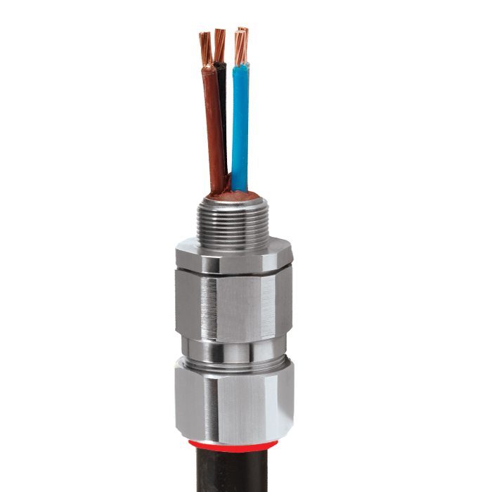
- PX2KW-US | Class I, Div 1 & 2 | AEx e, AEx d, AEx nR, AEx ta | Explosive Atmosphere Barrier Cable Gland
- Ex nR
- Ex ta
PX2KW-US | Class I, Div 1 & 2 | AEx e, AEx d, AEx nR, AEx ta | Explosive Atmosphere Barrier Cable Gland For all types of Steel & Aluminium Wire Armoured Cables
We'd like to keep in touch
We have some exciting things in the pipeline - if you'd like to be the first to know please enter your email address below.
Globally Approved, Explosive Atmosphere Barrier Cable Gland
• Metal-to-metal armour clamping
• Direct & remote installation
• Compound barrier type flameproof seal
• Controlled outer ‘load retention’ seal
• Unique OSTG prevents overtightening
• Integral protected deluge seal
• -76°F to +185°F
• Globally marked, IECEx, ATEX, UL & cCSAus
• EMC tested
• Compound barrier seals around internal cable cores after removing any inner cable sheath/bedding; completely eliminating any risk of coldflow.
For under / oversized armour wires click here
| Design Specification | BS 6121:Part 1:1989, IEC 62444, EN 62444 |
| Mechanical Classifications* | Impact = Level 8, Retention = Class B |
| Enclosure Protection | IK10 to IEC 62262 (20 joules) Brass & Stainless Steel only |
| Electrical Classifications * | Category B (Category A when used with braid, tape or pliable armour cables) |
| ATEX Certificate | CML 18ATEX1325X, CML 18ATEX4317X |
| Code of Protection | II 2G, II 1D, Ex db IIC Gb, Ex eb IIc Gb, Ex ta IIIC Da II 3G Ex nR IIC Gc, IM2 Ex db I Mb, Ex eb I Mb |
| Compliance Standards | EN 60079-0,1,7,15,31 |
| IECEx Certificate | IECEx CML 18.0182X |
| Code of Protection | Ex db IIC Gb, Ex eb IIC Gb, Ex nR IIC Gc, Ex ta IIIC Da, Ex db I, Ex eb I |
| Compliance Standards | IEC 60079-0,1,7,15,31 |
| cCSAus Certificate (20s16 - 100) | 2288626 |
| Code of Protection | Class I, Div. 2 Groups A, B, C and D; Class II, Div. 2 Groups F and G; Class III, Div. 2; Type 4X: Oil Resistant II: Class I, Zone 1 AEx d IIC Gb, AEx e IIC Gb, Class I, Zone 2 AEx nR IIC Gc, Class I, Zone 20 AEx ta IIIC Da |
| CSAus Code of Protection*** | Class I, Div. 1 and 2, Groups A, B, C and D; Class II, Div. 2 Groups F and G; Class III, Div. 2; Type 4X: Oil Resistant II: Class I, Zone 1, AEx d IIC Gb, AEx e IIC Gb; Class I, Zone 2, AEx nR IIC Gc |
| cCSA Code of Protection*** | Class I, Div. 2 Groups A, B, C and D; Class II, Div. 2 Groups F and G; Class III, Div. 2; Type 4X: Oil Resistant II: |
| Compliance Standards | CAN/CSA-C22.2 No 0,18,25,30,94,174, CAN/CSA-E60079-0,1,7,15,31 CAN/CSA-E61241-1-1 Part 1-1, ANSI/UL 514B Ed 5, ANSI/UL 50 Ed 11, ANSI/UL 2225 Ed 4, UL60079 |
| UL Certificate | E161256C |
| Code of Protection | Class I, Div 1, 2, Groups A,B,C,D; Class II, Div 1, 2, Groups E, F,G |
| Compliance Standards | UL 2225, CSA C22.2 No 174, UL 514B, CSA C22.2 No 18, CSA C22.2 No 30 |
| EAC Certificate (Formerly GOST R, K & B) | C-GB.A07.B.04595/22 |
| UkrSEPRO | CU 19.0371X |
| KCs Certificate | 14-GA4BO-0252X |
| CCOE / PESO (India) Certificate | Ex d: P548696, Ex e: P533772 |
| CCC Certificate | 2020322313003190 |
| INMETRO Approval | TÜV 12.2073X |
| RETIE Approval | 03866 |
| Marine Approvals | LRS: 01/00172, DNV: TAE00000Y, ABS: 20-LD1948801-PDA, BV: 43180/A1BV |
| Ingress Protection Rating** | IP66, IP67 & IP68 |
| Deluge Protection Compliance | DTS01 : 91 |
| NEMA Rating** | NEMA 4X** |
| Cable Gland Material | Electroless Nickel Plated Brass, Copper Free (<0.4%) Aluminium, Stainless Steel |
| Seal Material | CMP SOLO LSF Halogen Free Thermoset Elastomer / Epoxy Barrier Compound |
| Cable Type | Single/Served Wire Armour (SWA)*** |
| Armour Clamping | Detachable Compound Tube / Cone & AnyWay Universal Clamping Ring |
| Sealing Technique | Unique CMP ‘LRS’ Outer Seal (Load Retention Seal) |
| Sealing Area(s) | Inner Compound Barrier & Cable Outer Sheath |
| Optional Accessories | Locknuts, Earth Tags, Serrated Washers, Entry Thread Seals, Shrouds,Ingress Discs |
| Optional Installation Tools | Spanners, Armour Former Tool |
Note : * Mechanical & Electrical Classifications applied as per IEC 62444 & EN 62444
** When CMP installation accessories are used. Refer to Maintaining a Seal for further information.
*** Where the cable is permitted by code (NEC and/or CEC)
**** IP68 tested to a minimum depth of 30 metres for 12 hours, alternate depths / durations can be provided upon request
Certificates


Product Selection Table
Click here to view how to order
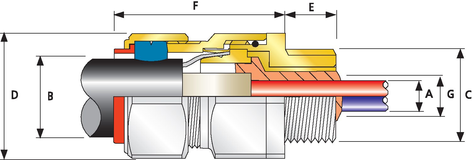
| Combined Ordering Reference (*Nickel Plated Brass NPT) | Available Entry Threads 'C' (Alternative Metric Thread Lengths Available) | Number of Cores | Diameter Over Conductors 'A' | Cable Bedding Diameter 'G' | Overall Cable Diameter 'B' | Armor Range | Across Flats 'D' | Across Corners 'D' | Protrusion Length 'F' | Shroud | Cable Gland Weight (oz) |
|||||||
| Size | Type | Ordering Suffix | NPT | NPT (Option) | Metric (Option) | Thread Length (NPT) 'E' | Max | Max | Min | Max | Min | Max | Max | Max | ||||
| 20S16 | PX2KW | 1RA531 | ½" | ¾" | M20 | 0.78 | 21 | 0.46 | 0.46 | 0.24 | 0.52 | 0.03 | 0.05 | 1.20 | 1.32 | 2.44 | PVC06 | 8.47 |
| 20S | PX2KW | 1RA531 | ½" | ¾" | M20 | 0.78 | 21 | 0.46 | 0.46 | 0.37 | 0.63 | 0.03 | 0.05 | 1.20 | 1.32 | 2.44 | PVC06 | 8.11 |
| 20 | PX2KW | 1RA531 | ½" | ¾" | M20 | 0.78 | 21 | 0.50 | 0.51 | 0.49 | 0.82 | 0.03 | 0.05 | 1.20 | 1.32 | 2.48 | PVC06 | 8.47 |
| 25S | PX2KW | 1RA532 | ¾" | 1" | M25 | 0.80 | 30 | 0.69 | 0.70 | 0.55 | 0.87 | 0.05 | 0.06 | 1.48 | 1.62 | 2.74 | PVC09 | 13.05 |
| 25 | PX2KW | 1RA532 | ¾" | 1" | M25 | 0.80 | 30 | 0.69 | 0.70 | 0.72 | 1.03 | 0.05 | 0.06 | 1.48 | 1.62 | 2.74 | PVC09 | 13.05 |
| 32 | PX2KW | 1RA533 | 1" | 1 ¼" | M32 | 0.98 | 38 | 0.93 | 0.94 | 0.93 | 1.34 | 0.06 | 0.08 | 1.81 | 1.99 | 2.95 | PVC11 | 20.11 |
| 40 | PX2KW | 1RA534 | 1 ¼" | 1 ½" | M40 | 1.01 | 59 | 1.18 | 1.19 | 1.10 | 1.59 | 0.06 | 0.08 | 2.17 | 2.38 | 2.95 | PVC15 | 28.22 |
| 50S | PX2KW | 1RA535 | 1 ½" | 2" | M50 | 1.03 | 89 | 1.44 | 1.45 | 1.39 | 1.84 | 0.08 | 0.10 | 2.36 | 2.60 | 3.03 | PVC18 | 31.75 |
| 50 | PX2KW | 1RA536 | 2" | 2 ½" | M50 | 1.06 | 115 | 1.61 | 1.63 | 1.59 | 2.09 | 0.08 | 0.10 | 2.76 | 3.04 | 3.03 | PVC21 | 41.98 |
| 63S | PX2KW | 1RA536 | 2" | 2 ½" | M63 | 1.06 | 115 | 1.89 | 1.88 | 1.80 | 2.34 | 0.08 | 0.10 | 2.95 | 3.25 | 3.14 | PVC23 | 49.03 |
| 63 | PX2KW | 1RA537 | 2 ½" | 3" | M63 | 1.57 | 115 | 2.11 | 2.13 | 2.15 | 2.59 | 0.08 | 0.10 | 3.15 | 3.46 | 3.16 | PVC25 | 49.74 |
| 75S | PX2KW | 1RA537 | 2 ½" | 3" | M75 | 1.57 | 140 | 2.36 | 2.37 | 2.32 | 2.84 | 0.08 | 0.10 | 3.54 | 3.90 | 3.42 | PVC28 | 73.72 |
| 75 | PX2KW | 1RA538 | 3" | 3 ½" | M75 | 1.63 | 140 | 2.53 | 2.53 | 2.63 | 3.09 | 0.10 | 0.12 | 3.94 | 4.33 | 3.48 | PVC30 | 89.60 |
| 90 | PX2KW | 1RA539 | 3 ½" | 4" | M90 | 1.69 | 140 | 2.97 | 2.98 | 3.00 | 3.56 | 0.12 | 0.16 | 4.50 | 4.95 | 4.02 | PVC32 | 130.87 |
| 100 | PX2KW | 1RA539 | 3 ½" | 4" | M100 | 1.69 | 200 | 3.29 | 3.38 | 3.39 | 3.99 | 0.12 | 0.16 | 5.24 | 5.76 | 4.49 | LSF33 | 169.67 |
| *Note : For material options please change the suffix in the ordering reference ; Brass (no suffix required), Nickel Plated Brass “5” (as standard), 316 Grade Stainless Steel “4”, Copper Free Aluminum “1” For NPT options please change the following digits after the material suffix ; ½” = 31, ¾” = 32, 1” = 33, 1 ¼” = 34, 1 ½” = 35, 2” = 36, 2 ½” = 37, 3” = 38, 3 ½” = 39, 4” = 310 (Brass requires prefix “0”) |
||||||||||||||||||
| Examples: 32PX2KW1RA534 = Nickel Plated Brass 1 ¼” NPT, 25PX2KW1RA432 = Stainless Steel ¾” NPT, 20PX2KW1RA5 Nickel Plated Brass M20 | ||||||||||||||||||
| Dimensions in inches unless otherwise stated | ||||||||||||||||||
| Cable Gland Size | Available Entry Threads 'C' (Alternative Metric Thread Lengths Available) | Number of Cores | Diameter Over Conductors 'A' | Cable Bedding Diameter 'G' | Overall Cable Diameter 'B' | Armor Range | Across Flats 'D' | Across Corners 'D' | Protrusion Length 'F' | Combined Ordering Reference (*Nickel Plated Brass NPT) | Shroud | Cable Gland Weight (Kgs) |
|||||||
| NPT | NPT (Option) | Metric (Option) | Thread Length (NPT) 'E' | Size | Type | Ordering Suffix | |||||||||||||
| 20S16 | ½' | ¾' | M20 | 19.8 | 21 | 11.7 | 11.7 | 6.1 | 13.2 | 0.8 | 1.25 | 30.5 | 33.5 | 62.0 | 20S16 | PX2KW | 1RA531 | PVC06 | 0.24 |
| 20S | ½' | ¾' | M20 | 19.8 | 21 | 11.7 | 11.7 | 9.4 | 16.0 | 0.8 | 1.25 | 30.5 | 33.5 | 62.0 | 20S | PX2KW | 1RA531 | PVC06 | 0.23 |
| 20 | ½' | ¾' | M20 | 19.8 | 21 | 12.7 | 13.0 | 12.4 | 20.8 | 0.8 | 1.25 | 30.5 | 33.5 | 63.0 | 20 | PX2KW | 1RA531 | PVC06 | 0.24 |
| 25S | ¾' | 1' | M25 | 20.3 | 30 | 17.5 | 17.8 | 14.0 | 22.1 | 1.25 | 1.6 | 37.6 | 41.1 | 69.6 | 25S | PX2KW | 1RA532 | PVC09 | 0.37 |
| 25 | ¾' | 1' | M25 | 20.3 | 30 | 17.5 | 17.8 | 18.3 | 26.2 | 1.25 | 1.6 | 37.6 | 41.1 | 69.6 | 25 | PX2KW | 1RA532 | PVC09 | 0.37 |
| 32 | 1' | 1 ¼' | M32 | 24.9 | 38 | 23.6 | 23.9 | 23.6 | 34.0 | 1.6 | 2.0 | 46.0 | 50.5 | 74.9 | 32 | PX2KW | 1RA533 | PVC11 | 0.57 |
| 40 | 1 ¼' | 1 ½' | M40 | 25.7 | 59 | 30.0 | 30.2 | 27.9 | 40.4 | 1.6 | 2.0 | 55.1 | 60.5 | 74.9 | 40 | PX2KW | 1RA534 | PVC15 | 0.80 |
| 50S | 1 ½' | 2' | M50 | 26.2 | 89 | 36.6 | 36.8 | 35.3 | 46.7 | 2.0 | 2.5 | 59.9 | 66.0 | 77.0 | 50S | PX2KW | 1RA535 | PVC18 | 0.90 |
| 50 | 2' | 2 ½' | M50 | 26.9 | 115 | 40.9 | 41.4 | 40.4 | 53.1 | 2.0 | 2.5 | 70.1 | 77.0 | 77.0 | 50 | PX2KW | 1RA536 | PVC21 | 1.19 |
| 63S | 2' | 2 ½' | M63 | 26.9 | 115 | 48.0 | 48.5 | 45.7 | 59.4 | 2.0 | 2.5 | 74.9 | 82.6 | 79.8 | 63S | PX2KW | 1RA536 | PVC23 | 1.39 |
| 63 | 2 ½' | 3' | M63 | 39.9 | 115 | 53.6 | 54.1 | 54.6 | 65.8 | 2.0 | 2.5 | 80.0 | 88.1 | 80.3 | 63 | PX2KW | 1RA537 | PVC25 | 1.41 |
| 75S | 2 ½' | 3' | M75 | 39.9 | 140 | 59.9 | 60.2 | 58.9 | 72.1 | 2.0 | 2.5 | 89.9 | 99.1 | 86.9 | 75S | PX2KW | 1RA537 | PVC28 | 2.09 |
| 75 | 3' | 3 ½' | M75 | 41.4 | 140 | 64.3 | 64.3 | 66.8 | 78.5 | 2.5 | 3.0 | 100.1 | 110.0 | 88.4 | 75 | PX2KW | 1RA538 | PVC30 | 2.54 |
| 90 | 3 ½' | 4' | M90 | 42.9 | 140 | 75.4 | 75.7 | 76.2 | 90.4 | 3.15 | 4.0 | 115.1 | 126.5 | 102.1 | 90 | PX2KW | 1RA539 | PVC32 | 3.71 |
| 100 | 3 ½' | 4' | M100 | 43.9 | 200 | 85.6 | 85.9 | 86.1 | 101.3 | 3.15 | 4.0 | 127.0 | 139.7 | 114.0 | 100 | PX2KW | 1RA5310 | LSF33 | 4.81 |
| Dimensions in millimeters unless otherwise stated | |||||||||||||||||||
Cable Gland Sizing – Cable Construction & Armour Wires
Cable glands conforming to British Standard BS 6121:1973 were specifically to cater for industry standard armour wire sizes and cable diameters found in British and international standard cables. These armour wire sizes have remained common to virtually all cables manufactured to BS, IEC and AS/NZS standards, and can be accommodated by some industrial cable glands to BS 6121 & IEC 62444 and explosive atmosphere certified cable glands to IEC 60079. There is an expectation that within a given armoured cable, all of the armour wires have the same consistent thickness so that cable glands utilising a cone and clamping ring can be correctly terminated and maintain their safety critical functional performance. If the armour wires in an armoured cable have significant differences in their thicknesses then it may be no surprise if consequent issues arise with their termination when using standard products. The correlation between the cable inner bedding diameter and the cable armour wire is clearly defined in IEC 60502-1 and AS/NZS 5000.1.
Read moreNon-Standard Armour Wire Sizing
Due to the global nature of cable manufacturing, and variations from one supply country to another CMP also provides alternative cable glands to suit cable armour wires which are outside of the standard range. This predominantly affects Single Wire Armour (SWA) cables and the data provided below is geared towards that type of cable. Most variations in braid thickness can be accommodated with standard product.
Read moreExplosion Protected Equipment
For equipment which is intended to be used in explosive atmospheres, a number of standard methods of protection against ignition have been established. These have been adopted into construction standards and codes, which allow manufacturers to make equipment of a uniform type and have this equipment tested and certified for compliance with the relevant standards.
Read moreVisit our Knowledge Base for technical expertise and advice, gathered over CMP's 60+ years' experience in the art of terminating cable glands.
Log in now