- Home
- Cable Cleats for Electrical Installations
- Technical
- Recommended Cleat Spacings
- Multiphysics Model
- Certificate Downloads
- Cable Cleat Accessories
- Cable Cleat Nut Spacer
- Cable Cleat Selection
- Cable Formations
- Catalogue Downloads
- Recommended Cleat Spacings
- Cleat Fixing Packs
- Fire Performance
- Galvanic Corrosion
- Good Installation Practices
- How To Order
- Intermediate Restraints
- Materials
- Product Downloads
- Product Overview
- Resistance Classifications
- Twin arc profiles
- What is a Cable Cleat?
- What is a Short Circuit?
- Why use a Cable Cleat?
Need more help? Contact our team on +44 191 265 7411
A Multiphysics Model of Trefoil Cable Cleats during Short Circuit – Courtesy of Continuum Blue
Trefoil cable formation is used where three phases are carried by three single core power cables, rather than a single multicore cable.
The advantage of installing three single core cables in such a configuration is that it minimises the induction of eddy currents, therefore reducing the effect of localised heating, whilst maintaining the current carrying capacity of the circuit. Trefoil cable cleats are devices used to hold the three single core power cables in a triangular touching (trefoil) formation, along the length of the laid cables.
Short circuit fault conditions of single core cables in trefoil formation result in high dynamic electromagnetic forces; these forces need to be restrained correctly in order to prevent extensive damage to the cable management system, and more importantly potential injury.
Manufacturers of trefoil cable cleats are required to physically test their designs in an applied test, where a section of three single core power cables are held with the cable cleats and then exposed to a three phase short circuit.
Each assembly of cable cleat, cable and applied current will yield a different result, so in theory an infinite number of tests are required. These physical tests can be costly in terms of both expense and time.
To avoid the inevitable delays in testing all of the possible permutations that may arise, a time-dependent multiphysics model including currents, induced electromagnetic forces, material plasticity and contact analysis has been set up. This can fully describe and simulate the dynamic load conditions on the cables and cable cleats during a short circuit fault condition.
This multiphysics model can be used to test and assess various cable cleat designs during a short circuit, in a fraction of the time taken to set up and carry out a physical short circuit test.
Every parameter is taken into consideration in the model such as peak fault current, cable diameter, conductor size and type, insulation thickness, cable cleat and liner material properties, cable cleat spacing etc.
Example outputs of the model are shown below:
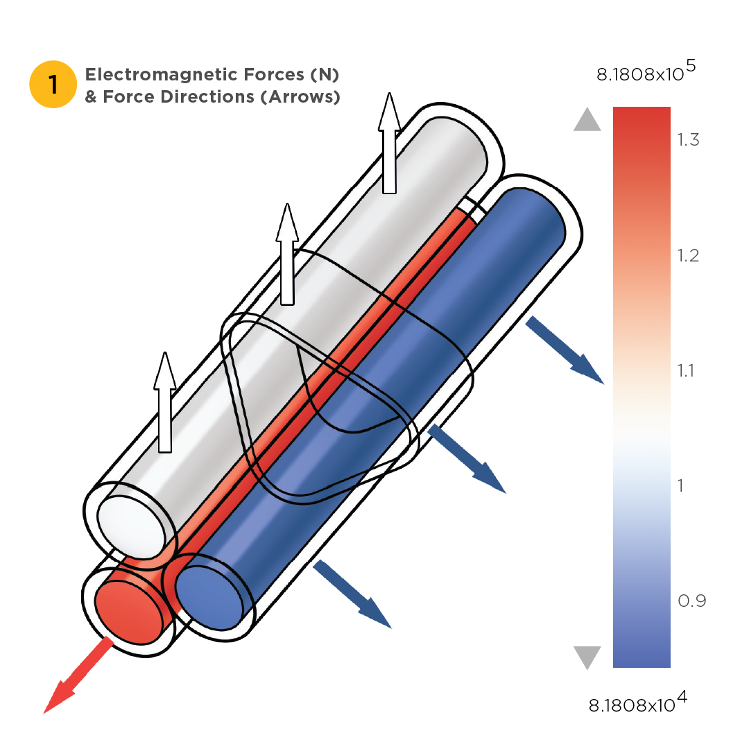
![]() The electromechanical forces in Newtons, coupled with arrows showing the vector direction of forces acting upon each cable conductor at a specified point in time during the short circuit.
The electromechanical forces in Newtons, coupled with arrows showing the vector direction of forces acting upon each cable conductor at a specified point in time during the short circuit.
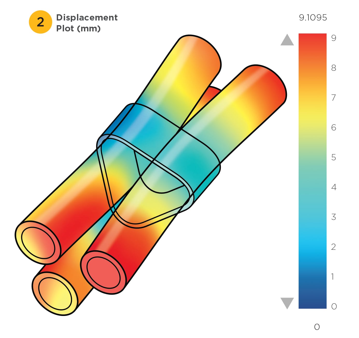
![]() The displacement magnitude in mm of the cables caused by the electromagnetic forces acting upon them.
The displacement magnitude in mm of the cables caused by the electromagnetic forces acting upon them.
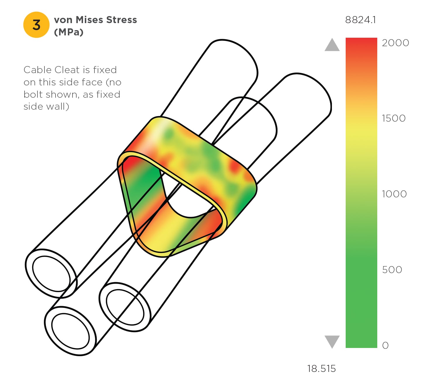
![]() The von Mises stress in MPa of the cable cleat material caused by the cable displacement and dynamic load.
The von Mises stress in MPa of the cable cleat material caused by the cable displacement and dynamic load.
Comparisons between the model outputs, physical test data, and calculations given in the test standard, show an excellent correlation. Once the user inputs their defined parameters, the model calculates and displays the outputs which quickly indicate whether or not the selected cable cleat is safe enough to use in that particular application.