- Home
- Cable Glands
- Products
- American NEC & CEC
- TMC | Class II, Div 1 & 2 | AEx e | Hazardous Location Cable Gland
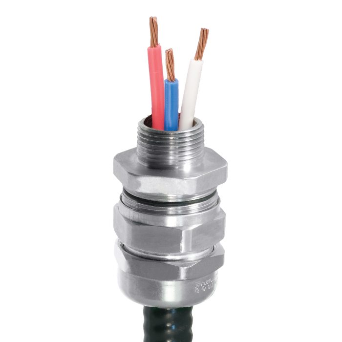
TMC | Class II, Div 1 & 2 | AEx e | Hazardous Location Cable Gland For MC, MC-HL, Interlocked & Teck Armoured Cables
We'd like to keep in touch
We have some exciting things in the pipeline - if you'd like to be the first to know please enter your email address below.
Globally Approved, Hazardous (Classified) Location Cable Gland
- Simple, sequential installation process
- No disassembly required
- Integral protected deluge seal
- 360° grounding spring
- -76°F to 230°F
- Class I Zone 1, 21 and Zone 2, 22
- Class I Zone 1 Ex e & Class I Division 2 ABCD
- Globally marked, UL, cCSAus, IECEx & ATEX
Please note the following installation requirements:
1) Where explosionproof enclosures are being used the TMC must be installed with an approved pouring or compound sealing fitting. In Division 2 locations the TMC can be fitted directly to an enclosure which has no source of ignition in accordance with NEC/CEC requirements.
2) Glands with NPT entry threads are suitable for both Divisions and Zones.
3) Glands with Metric entry threads are suitable for Zones only unless fitted with an approved NPT male adaptor in accordance with CEC requirements.
| Design Specification | BS 6121:Part 1:1989, IEC 62444, EN 62444 |
| Mechanical Classifications* | Impact = Level 8, Retention = Class D |
| Enclosure Protection | IK10 to IEC 62262 (20 joules) Brass & Stainless Steel only |
| ATEX Certificate | CML 18ATEX1337X |
| Code of Protection | II 2G 1D, Ex eb II Gb, Ex ta IIIC Da IP66 |
| Compliance Standards | EN 60079-0,7, EN 61241-0,1 |
| IECEx Certificate | IECEx CML 18.0184X |
| Code of Protection | Ex eb II Gb, Ex ta IIIC Da IP66 |
| Compliance Standards | IEC 60079-0,7,31 |
| cCSAus Certificate | 1129339 |
| CSAus Code of Protection | Class II, Div 1 and 2, Groups E, F, and G; Class III, Div 1 and 2; Encl. Type 3, 4, 4X. Class I, Zone 1, AEx e II; Note: This product is suitable for Class I, Division 2 applications, when installed as per NEC 501.10(B)(4) |
| cCSA Code of Protection | Class II, Div 1 and 2, Groups E, F, and G; Class III, Div 1 and 2; Encl. Type 3, 4, 4X, Class I, Zone I, Ex e II; Note: This product is suitable for Class I, Division 2 applications, when installed as per Canadian Electrical Code J18-150 & J18-152 |
| Compliance Standards | CAN/CSA-C22.2 Various Sections (See Certificate) CAN/CSA-E60079-0, IEC 60079-0 |
| UL Certificate | E256366 |
| Code of Protection | Class I, Zone 1, AEx e II |
| Compliance Standards | UL 514B, UL 60079-0,7, U 2225 |
| EAC Certificate (Formerly GOST R, K & B) | TC RU C-GB.AA87.B.00487 |
| UkrSEPRO | CU 19.0371X |
| CCOE / PESO (India) Certificate | Ex e: P533772 |
| CCC Certificate | 2020322313003429 |
| Marine Approvals | LRS: 01/00172, DNV: TAE00000Y, ABS: 20-LD1948801-PDA, BV: 43180/A1BV |
| Ingress Protection Rating** | NEMA 4X & IP66 |
| Cable Gland Material | Copper Free Aluminium (<0.4%), Electroless Nickel Plated Brass, Stainless Steel |
| Seal Material | CMP SOLO LSF Halogen Free Thermoset Elastomer |
| Cable Type | Corrugated & Interlocked Metal Clad Armour (MC) or TECK90, Continuously Welded Metal Clad Armour (MCHL), ACIC-HL, ACWU90-HL, RC90-HL, RA90-HL |
| Armour Clamping | 360° Stainless Steel Grounding Spring (non-magnetic) |
| Sealing Technique | CMP Load Retention Seal |
| Sealing Area(s) | Cable Outer Jacket |
| ECAS Certificate | E23-02-065468 |
Note : * Mechanical & Electrical Classifications applied as per IEC 62444 & EN 62444
** When CMP installation accessories are used. Refer to Maintaining a Seal for further information.
Certificates


Product Selection Table
Click here to view how to order
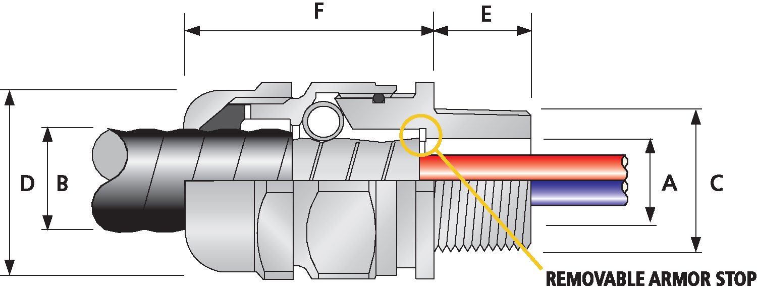
| Order Reference (NPT) | Entry Thread 'C' | Minimum Thread Length 'E' | Minimum Thread Length 'E' | Cable Armor Diameter 'A' | Cable Jacket Diameter 'B' | Nominal Assembly Length 'F' | Max | Shroud | Weight (oz) | ||||||||
| End Stop In | End Stop Out | ||||||||||||||||
| Aluminum | Nickel Plated Brass | Stainless Steel | NPT | Metric | NPT | Metric | Min | Max | Min | Max | Min | Max | Across Flats 'D' | Across Corners 'D' | |||
| TMC050SA | TMC050SNB | TMC050SSS | ½" | M20 | 0.78 | 0.59 | No Stop | No Stop | 0.34 | 0.50 | 0.35 | 0.55 | 1.83 | 1.20 | 1.32 | PVC06 | 7.90 |
| TMC050A | TMC050NB | TMC050SS | ½" | M20 | 0.78 | 0.59 | No Stop | No Stop | 0.51 | 0.67 | 0.55 | 0.79 | 2.06 | 1.42 | 1.56 | PVC09 | 9.91 |
| TMC075A | TMC075NB | TMC075SS | ¾" | M25 | 0.80 | 0.59 | 0.59 | 0.76 | 0.76 | 0.92 | 0.67 | 1.04 | 2.09 | 1.61 | 1.78 | PVC10 | 11.61 |
| TMC100A | TMC100NB | TMC100SS | 1" | M32 | 0.98 | 0.59 | 0.78 | 0.97 | 0.97 | 1.15 | 0.91 | 1.27 | 2.24 | 1.97 | 2.17 | PVC13 | 17.53 |
| TMC125A | TMC125NB | TMC125SS | 1 ¼" | M40 | 1.01 | 0.59 | 1.08 | 1.23 | 1.23 | 1.39 | 1.16 | 1.50 | 2.22 | 2.17 | 2.38 | PVC15 | 20.92 |
| TMC150A | TMC150NB | TMC150SS | 1 ½" | M50 | 1.03 | 0.59 | 1.32 | 1.46 | 1.46 | 1.62 | 1.40 | 1.74 | 2.31 | 2.36 | 2.60 | PVC18 | 24.45 |
| TMC200SA | TMC200SNB | TMC200SSS | 2" | M50 | 1.06 | 0.59 | 1.51 | 1.68 | 1.68 | 1.85 | 1.58 | 1.97 | 2.52 | 2.76 | 3.03 | PVC21 | 42.33 |
| TMC200A | TMC200NB | TMC200SS | 2" | M63 | 1.06 | 0.59 | 1.77 | 1.93 | 1.93 | 2.09 | 1.86 | 2.21 | 2.49 | 2.95 | 3.25 | PVC23 | 38.80 |
| TMC250SA | TMC250SNB | TMC250SSS | 2 ½" | M75 | 1.57 | 0.59 | 2.05 | 2.16 | 2.16 | 2.32 | 2.08 | 2.44 | 2.73 | 3.15 | 3.47 | PVC25 | 59.97 |
| TMC250A | TMC250NB | TMC250SS | 2 ½" | M75 | 1.57 | 0.59 | 2.25 | 2.41 | 2.41 | 2.55 | 2.33 | 2.68 | 2.84 | 3.35 | 3.68 | PVC27 | 56.48 |
| TMC300A | TMC300NB | TMC300SS | 3" | M90 | 1.63 | 0.59 | 2.54 | 2.78 | 2.78 | 2.97 | 2.62 | 3.13 | 3.87 | 4.33 | 4.76 | LSF32 | 123.46 |
| TMC350A | TMC350NB | TMC350SS | 3½" | M100 | 1.69 | 0.95 | 2.91 | 3.29 | 3.29 | 3.49 | 2.99 | 3.83 | 4.63 | 5.25 | 5.78 | LSF34 | 236.34 |
| Dimensions displayed in inches unless otherwise stated | |||||||||||||||||
| Order Reference (NPT) | Entry Thread 'C' | Minimum Thread Length 'E' | Minimum Thread Length 'E' | Cable Armor Diameter 'A' | Cable Jacket Diameter 'B' | Nominal Assembly Length 'F' | Max | Shroud | Weight (Kgs) |
||||||||
| End Stop In | End Stop Out | ||||||||||||||||
| Aluminum | Nickel Plated Brass | Stainless Steel | NPT | Metric | NPT | Metric | Min | Max | Min | Max | Min | Max | Across Flats 'D' | Across Corners 'D' |
|||
| TMC050SA | TMC050SNB | TMC050SSS | ½' | M20 | 19.8 | 15.0 | No Stop | No Stop | 8.6 | 12.7 | 8.9 | 14.0 | 46.5 | 30.5 | 33.5 | PVC06 | 0.22 |
| TMC050A | TMC050NB | TMC050SS | ½' | M20 | 19.8 | 15.0 | No Stop | No Stop | 13.0 | 17.0 | 11.2 | 20.1 | 52.3 | 36.1 | 39.6 | PVC09 | 0.28 |
| TMC075A | TMC075NB | TMC075SS | ¾' | M25 | 20.3 | 15.0 | 15.0 | 19.3 | 19.3 | 23.4 | 17.0 | 26.4 | 53.1 | 40.9 | 45.2 | PVC10 | 0.33 |
| TMC100A | TMC100NB | TMC100SS | 1' | M32 | 24.9 | 15.0 | 19.8 | 24.6 | 24.6 | 29.2 | 22.1 | 32.3 | 56.9 | 50.0 | 55.1 | PVC13 | 0.50 |
| TMC125A | TMC125NB | TMC125SS | 1 ¼' | M40 | 25.7 | 15.0 | 27.4 | 31.2 | 31.2 | 35.3 | 29.5 | 38.1 | 56.4 | 55.1 | 60.5 | PVC15 | 0.59 |
| TMC150A | TMC150NB | TMC150SS | 1 ½' | M50 | 26.2 | 15.0 | 33.5 | 37.1 | 37.1 | 41.1 | 35.6 | 44.2 | 58.7 | 59.9 | 66.0 | PVC18 | 0.69 |
| TMC200SA | TMC200SNB | TMC200SSS | 2' | M50 | 26.9 | 15.0 | 38.4 | 42.7 | 42.7 | 47.0 | 40.1 | 50.0 | 64.0 | 70.1 | 77.0 | PVC21 | 1.20 |
| TMC200A | TMC200NB | TMC200SS | 2' | M63 | 26.9 | 15.0 | 45.0 | 49.0 | 49.0 | 53.1 | 47.2 | 56.1 | 63.2 | 74.9 | 82.6 | PVC23 | 1.10 |
| TMC250SA | TMC250SNB | TMC250SSS | 2 ½' | M75 | 39.9 | 15.0 | 52.1 | 54.9 | 54.9 | 58.9 | 52.8 | 62.0 | 69.3 | 80.0 | 88.1 | PVC25 | 1.70 |
| TMC250A | TMC250NB | TMC250SS | 2 ½' | M75 | 39.9 | 15.0 | 57.2 | 61.2 | 61.2 | 64.8 | 59.2 | 68.1 | 72.1 | 85.1 | 93.5 | PVC27 | 1.60 |
| TMC300A | TMC300NB | TMC300SS | 3' | M90 | 41.4 | 15.0 | 64.5 | 70.6 | 70.6 | 75.4 | 66.5 | 79.5 | 98.3 | 110.0 | 120.9 | LSF32 | 3.50 |
| TMC350A | TMC350NB | TMC350SS | 3½' | M100 | 42.9 | 24.1 | 73.9 | 83.6 | 83.6 | 88.6 | 75.9 | 97.3 | 117.6 | 133.4 | 146.8 | LSF34 | 6.70 |
| TMC400A | TMC400NB | TMC400SS | 4' | M115 | 43.9 | 24.1 | 73.9 | 83.6 | 83.6 | 88.6 | 75.9 | 97.3 | 124.0 | 133.4 | 146.8 | LSF34 | 7.50 |
| Dimensions displayed in millimeters unless otherwise stated | |||||||||||||||||
Material Selection & Preservation for Longevity of Service
The selection of material by a customer often comes down to either carefully developed client specifications; cost / value options; or a combination of both. There will be numerous applications where the material selection is a lot more critical than it is in others.
Read moreTypical cable gland selection
Follow CMP's flowchart for guidance on how to select a cable gland based on your application and cable type.
Read moreCable Gland Construction utilising Displacement Seal
This type of sealing ring is usually employed in a cable gland that utilises a 3 stage sequential make off, where the tightening of the braid or armour termination is separated from the activation of the inner sealing ring.
Read moreVisit our Knowledge Base for technical expertise and advice, gathered over CMP's 60+ years' experience in the art of terminating cable glands.
Log in now