- Home
- Cable Glands
- Products
- Industrial / General Purpose
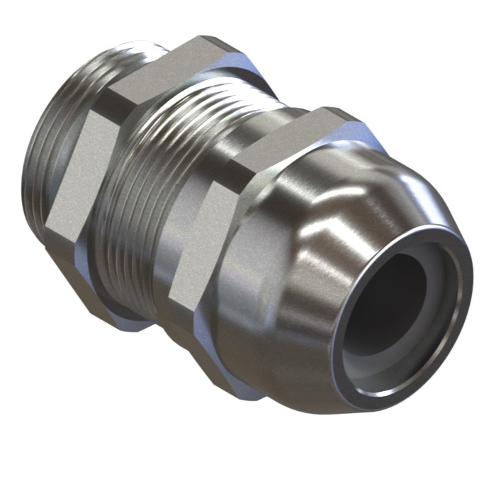
- TSM | Strain Relief Metal Cable Gland
-
IP66, 67, 68, 69K
-
+105°C to -60°C
TSM | Strain Relief Metal Cable Gland For All Types of Unarmoured & Braided / Screened Cables
We'd like to keep in touch
We have some exciting things in the pipeline - if you'd like to be the first to know please enter your email address below.
The TSM range of strain relief metal cable glands are suitable for use in industrial (safe) areas with unarmoured or braided cable, and have a temperature rating of +105°c to -60°c.
With the widest cable sealing range on the market, the TSM reduces the need to purchase a range of different sized cable glands for a project, reducing the overall cost.
The TSM range meets the requirements of well-known cable gland standards including EN 62444 and IEC 62444.
For more specific applications IP68 & IP69K ingress discs or plugs are available.
Features include:
- Unique strain relief sealing system
- Third party certified to IEC/EN 62444
- Widest cable range take on the market
- Easy to install
- Robust design, high quality materials
- O-ring interface seal included as standard
- Transit disc or IP68, IP69 and IP69K rated IP plug options available
- Product supplied in nickel-plated brass, or stainless steel on request
- Nickel-plated brass locknut available (ordering suffix 2TN)
Tightening tools may be required to aid installation. For further information, please click here.
| Design Specification | IEC 62444, EN 62444 (EN Metric only) |
| Mechanical Classifications* | Impact = Level 6, Cable Anchorage = Type A |
| Enclosure Protection | IK08 to IEC 62262 (7 joules) |
| Ingress Protection Rating ** | IP66, IP67, IP68**, IP69 and IP69K |
| Cable Gland Material | Nickel-plated brass, Stainless Steel (option) |
| Seal Material | CMP SOLO LSF Halogen-free Thermoset Elastomer |
| Cable Type | Unarmoured and Braided (when braid is terminate inside enclosure) |
| Sealing Technique | CMP unique strain relief sealing system |
| Sealing Area(s) | Cable Outer Sheath |
* Mechanical classifications applied as per IEC/EN 62444
** IP68 tested to 300 kPa for 16 hours (equivalent to 30 metres water depth)
Certificates

Click here to view how to order
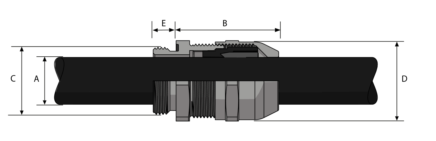
| DUAL SEAL | AVAILABLE ENTRY THREADS ‘C’ | OVERALL CABLE DIAMETER ‘A’ | ACROSS FLATS ‘D’ | ACROSS CORNERS ‘D’ | PROTRUSION LENGTH ‘B’ | WEIGHT GLAND ONLY † (KG) |
||||||
| STANDARD | OPTION | |||||||||||
| CABLE GLAND ONLY | CABLE GLAND WITH LOCKNUT | METRIC | THREAD LENGTH (METRIC) ‘E’ | LONG THREAD LENGTH (METRIC) ‘E’ | NPT | THREAD LENGTH (NPT) ‘E’ | MIN | MAX | MAX | MAX | ||
| 16DTSM1TA5 | 16DTSM2TN5 | M16 | 6.0 | 12.0 | 3⁄8” | 11.0 | 3.0 | 10.0 | 20.0 | 22.0 | 23.6 | 0.033 |
| 20DTSM1TA5 | 20DTSM2TN5 | M20 | 6.5 | 12.0 | 1⁄2” | 14.0 | 5.0 | 14.0 | 24.0 | 26.4 | 26.7 | 0.046 |
| 25DTSM1TA5 | 25DTSM2TN5 | M25 | 7.0 | 12.0 | 3⁄4” | 15.0 | 9.0 | 18.0 | 30.0 | 33.0 | 32.0 | 0.081 |
| 32DTSM1TA5 | 32DTSM2TN5 | M32 | 8.0 | 12.0 | 1” | 18.0 | 12.5 | 25.0 | 39.0 | 42.9 | 37.8 | 0.134 |
| 40DTSM1TA5 | 40DTSM2TN5 | M40 | 8.0 | 15.0 | 1 1⁄4” | 18.0 | 19.0 | 32.0 | 50.0 | 55.0 | 44.7 | 0.252 |
| 50DTSM1TA5 | 50DTSM2TN5 | M50 | 9.0 | 15.0 | 1 1⁄2” | 19.0 | 22.0 | 38.0 | 57.0 | 62.7 | 48.7 | 0.347 |
| 63DTSM1TA5 | 63DTSM2TN5 | M63 | 10.0 | 15.0 | 2” | 20.0 | 28.0 | 48.0 | 68.0 | 74.8 | 52.2 | 0.503 |
| STANDARD SEAL | AVAILABLE ENTRY THREADS ‘C’ | OVERALL CABLE DIAMETER ‘A’ | ACROSS FLATS ‘D’ | ACROSS CORNERS ‘D’ | PROTRUSION LENGTH ‘B’ | WEIGHT GLAND ONLY † (KG) |
||||||
| STANDARD | OPTION | |||||||||||
| CABLE GLAND ONLY | CABLE GLAND WITH LOCKNUT | METRIC | THREAD LENGTH (METRIC) ‘E’ | LONG THREAD LENGTH (METRIC) ‘E’ | NPT | THREAD LENGTH (NPT) ‘E’ | MIN | MAX | MAX | MAX | ||
| 12TSM1TA5 | 12TSM2TN5 | M12 | 6.0 | 12.0 | 1⁄4” | 11.0 | 3.0 | 6.5 | 16.0 | 17.6 | 22.3 | 0.020 |
| 16STSM1TA5 | 16STSM2TN5 | M16 | 6.0 | 12.0 | 3⁄8” | 11.0 | 3.0 | 7.0 | 20.0 | 22.0 | 23.6 | 0.032 |
| 16TSM1TA5 | 16TSM2TN5 | M16 | 6.0 | 12.0 | 3⁄8” | 11.0 | 6.0 | 10.0 | 20.0 | 22.0 | 23.6 | 0.032 |
| 20STSM1TA5 | 20STSM2TN5 | M20 | 6.5 | 12.0 | 1⁄2” | 14.0 | 5.0 | 10.0 | 24.0 | 26.4 | 26.7 | 0.046 |
| 20TSM1TA5 | 20TSM2TN5 | M20 | 6.5 | 12.0 | 1⁄2” | 14.0 | 9.0 | 14.0 | 24.0 | 26.4 | 26.7 | 0.045 |
| 25STSM1TA5 | 25STSM2TN5 | M25 | 7.0 | 12.0 | 3⁄4” | 15.0 | 9.0 | 15.5 | 30.0 | 33.0 | 32.0 | 0.081 |
| 25TSM1TA5 | 25TSM2TN5 | M25 | 7.0 | 12.0 | 3⁄4” | 15.0 | 12.5 | 18.0 | 30.0 | 33.0 | 32.0 | 0.080 |
| 32STSM1TA5 | 32STSM2TN5 | M32 | 8.0 | 12.0 | 1” | 18.0 | 12.5 | 19.0 | 39.0 | 42.9 | 37.8 | 0.133 |
| 32TSM1TA5 | 32TSM2TN5 | M32 | 8.0 | 12.0 | 1” | 18.0 | 17.0 | 25.0 | 39.0 | 42.9 | 37.8 | 0.130 |
| 40STSM1TA5 | 40STSM2TN5 | M40 | 8.0 | 15.0 | 1 1⁄4” | 18.0 | 19.0 | 27.0 | 50.0 | 55.0 | 44.7 | 0.251 |
| 40TSM1TA5 | 40TSM2TN5 | M40 | 8.0 | 15.0 | 1 1⁄4” | 18.0 | 24.0 | 32.0 | 50.0 | 55.0 | 44.7 | 0.250 |
| 50STSM1TA5 | 50STSM2TN5 | M50 | 9.0 | 15.0 | 1 1⁄2” | 19.0 | 22.0 | 32.0 | 57.0 | 62.7 | 48.7 | 0.346 |
| 50TSM1TA5 | 50TSM2TN5 | M50 | 9.0 | 15.0 | 1 1⁄2” | 19.0 | 28.0 | 38.0 | 57.0 | 62.7 | 48.7 | 0.340 |
| 63STSM1TA5 | 63STSM2TN5 | M63 | 10.0 | 15.0 | 2” | 20.0 | 28.0 | 39.0 | 68.0 | 74.8 | 52.2 | 0.501 |
| 63TSM1TA5 | 63TSM2TN5 | M63 | 10.0 | 15.0 | 2” | 20.0 | 37.0 | 48.0 | 68.0 | 74.8 | 52.2 | 0.489 |
| Part numbers in table are for standard metric entry threads. For guidance ordering alternate materials or alternate thread types, please contact your CMP sales representative. | ||||||||||||
| † Weight displayed for standard metric entry thread only | ||||||||||||
| For MOQ please contact CMP directly. | ||||||||||||
| Dimensions displayed in mm unless otherwise specified | ||||||||||||
Protection by Enclosure Against Mechanical Impact
It is critically important that enclosures afford a level of mechanical protection relevant to the area of installation that provides optimum electrical and operational safety. The international standard IEC 62262 covering ‘Degrees of protection provided by enclosures for electrical equipment against external mechanical impacts (IK Code)’ outlines the requirements for testing and rating of enclosures of different materials, so that careful selection to suit the application can be achieved.
Read moreDIN 40050 Definitions
The following page provides an explanation of ingress protection codes according to DIN 40050-9 (liquids) and IEC 60529 (dusts).
Read moreArea Classification Plan
A set of documents providing information on the explosive atmospheres of the plant as a minimum should comprise of: - Area classification drawings - A set of drawings showing to scale the complete layout of the facility, marking the extensions of the explosive atmospheres defined based on the - specific data associated with the flammable substances, sources of release and areas of risk for all elevations - Details of the flammable substances being stored, handled, or processed - Details of the sources of release - Information on the areas of risk - Information relating to the ventilation and air conditioning design in enclosed spaces, which affects the classification and extent of explosive atmospheres.
Read moreVisit our Knowledge Base for technical expertise and advice, gathered over CMP's 60+ years' experience in the art of terminating cable glands.
Sign up now