- Home
- Cable Glands
- Products
- Industrial / General Purpose
- FORTRA CTU | Industrial Cable Gland
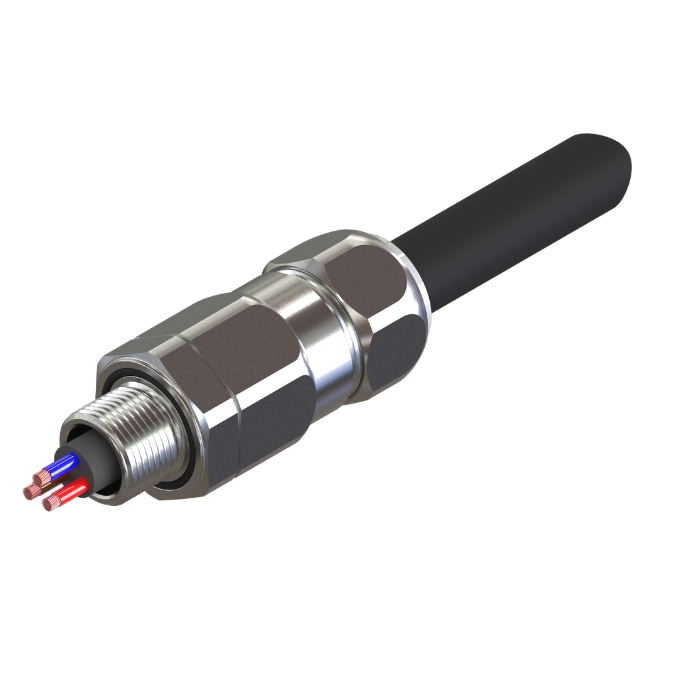
FORTRA CTU | Industrial Cable Gland For All Types of Armoured & Braided / Screened Cables
- Ex ta
FORTRA CTU | Industrial Cable Gland For All Types of Armoured & Braided / Screened Cables
We'd like to keep in touch
We have some exciting things in the pipeline - if you'd like to be the first to know please enter your email address below.
- Unique patented captive ‘Adaptive Cone’ for all types of armour or braid, with captive ‘AnyWay’ clamping ring
- Metal-to-metal armour clamping; no installation or inspection ambiguity
- Fewer installation steps for faster process. Unique ‘Quick’ Thread for faster armour clamping
- Outer seal with wider cable acceptance, meaning fewer stocking sizes
- IP66, 67, 68, 69 & 69K as standard with fully enclosed/protected deluge seal for third party compliance to DTS 01:91 & NEMA 4X & 6P
- Compact design; ideal for applications with limited installation space
- Fewer tools required for installation and maintenance
| Design Specification | BS 6121-1, IEC 62444, EN 62444 |
| Mechanical Classifications* | 16 -20S Impact = Category 6, 20 -130 Impact = Category 8, Wire Armour Anchorage = Type D, Braid Anchorage = Type C |
| Enclosure Protection | 16-20S IK08 to IEC 62262 (7 joules) 20-130 IK10 to IEC 62262 (20 joules) |
| Electrical Classifications * | Category B (Category A when used with braid, tape or pliable wire armour cables) |
| Ingress Protection Rating** | IP66, IP67, IP68***, IP69 and IP69K |
| Type Rating** | NEMA 4X & 6P |
| Deluge Protection Compliance | DTS 01:91 |
| Temperature for permanent application | -60 to +130 °C |
| Armour Clamping | Captive ‘Adaptive’ Armour Cone and Captive ‘AnyWay’ Clamping Ring |
| Seal Material | LSF Halogen Free Silicone |
| Sealing Technique | Outer Environmental/Load Retention Seal |
| Sealing Area(s) | Cable Outer Sheath |
| Type Material Options | Brass†, Electroless Nickel Plated Brass, Stainless Steel |
| Cable Type (s) | W: Single Wire Armour (SWA), Aluminium Wire Armour (AWA) X: Pliable Wire Armour (PWA), Steel Tape Armour (STA), Wire Braid Armour (e.g. SWB), Aluminium Strip Armour (ASA), Screened Flexible (EMC) Wire Braid (e.g. CY / SY), Armoured & Jacketed. |
| Marine Approvals | Lloyds: LR22320255TA, ABS: 25-0285992-PDA, DNV: TAE0000457, BV: 43180 |
| Industrial Certificate | CML 24CA17921 |
* Mechanical and Electrical Classifications applied as per IEC 62444 and EN 62444
** When CMP installation accessories are used. Refer to www.cmp-products.com for further information
*** IP68 tested to a depth of 30 metres for 7 days, alternative depths / durations can be provided on request
† Not available with NEMA type 4X and 6P
Certificates






Product Selection Table
Click here to view how to order
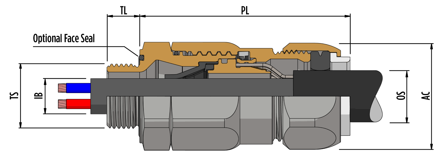
| Combined Ordering Reference | Entry Thread Size ‘TS’ | Entry Thread Pitch | Minimum Thread Length ‘TL’ | Overall Cable Diameter ‘OS’ | Armour Thickness | Max Across Flats | Max Across Corners ‘AC’ | Max Protrusion Length ‘PL’ | Shroud Size | Assembly Weight (oz) |
||||||
| Size | Type | Ordering Suffix | Min | Max | W Cable Type | X Cable Type | ||||||||||
| Mix | Max | Min | Max | |||||||||||||
| 20S16‡ | CTU | 502 | M20 | 0.06 | 0.59 | 0.24 | 0.52 | 0.03 | 0.05 | 0.01 | 0.04 | 0.94 | 1.04 | 2.05 | 4 | 0.09 |
| 20S‡ | CTU | 502 | M20 | 0.06 | 0.59 | 0.37 | 0.63 | 0.03 | 0.05 | 0.01 | 0.04 | 0.94 | 1.04 | 2.05 | 4 | 0.08 |
| 20 | CTU | 502 | M20 | 0.06 | 0.59 | 0.49 | 0.82 | 0.03 | 0.05 | 0.02 | 0.05 | 1.2 | 1.32 | 1.97 | 6 | 0.12 |
| 25 | CTU | 503 | M25 | 0.06 | 0.59 | 0.63 | 1.03 | 0.05 | 0.06 | 0.02 | 0.05 | 1.48 | 1.63 | 2.46 | 9 | 0.23 |
| 32 | CTU | 504 | M32 | 0.06 | 0.59 | 0.85 | 1.33 | 0.06 | 0.08 | 0.02 | 0.05 | 1.81 | 1.99 | 2.62 | 11 | 0.34 |
| 40 | CTU | 505 | M40 | 0.06 | 0.59 | 1.1 | 1.59 | 0.06 | 0.08 | 0.02 | 0.06 | 2.17 | 2.38 | 2.81 | 15 | 0.51 |
| 50 | CTU | 506 | M50 | 0.06 | 0.59 | 1.5 | 2.09 | 0.08 | 0.1 | 0.02 | 0.06 | 2.76 | 3.03 | 2.93 | 21 | 0.78 |
| 63 | CTU | 507 | M63 | 0.06 | 0.59 | 2.05 | 2.6 | 0.08 | 0.1 | 0.02 | 0.06 | 3.15 | 3.46 | 3.37 | 25 | 0.98 |
| 75 | CTU | 508 | M75 | 0.06 | 0.59 | 2.54 | 3.09 | 0.1 | 0.12 | 0.02 | 0.06 | 3.94 | 4.33 | 3.54 | 30 | 1.84 |
| 90 | CTU | 509 | M90 | 0.08 | 0.94 | 2.95 | 3.56 | 0.12 | 0.16 | 0.03 | 0.06 | 4.49 | 4.94 | 5.25 | 32 | 3.73 |
| 100 | CTU | 5010 | M100 | 0.08 | 0.94 | 3.39 | 4 | 0.12 | 0.16 | 0.03 | 0.06 | 4.84 | 5.33 | 4.96 | 33 | 3.37 |
| 115 | CTU | 5011 | M115 | 0.08 | 0.94 | 3.98 | 4.35 | 0.12 | 0.16 | 0.03 | 0.06 | 5.24 | 5.76 | 5.53 | 34 | 4.74 |
| 130 | CTU | 5012 | M130 | 0.08 | 0.94 | 4.33 | 4.86 | 0.12 | 0.16 | 0.03 | 0.06 | 6.02 | 6.63 | 5.53 | 35 | 6.22 |
| Dimensions listed are for cable glands with metric equipment entry threads only. Alternative entry thread types e.g. NPT are available; dimensions may vary. | ||||||||||||||||
| Part numbers listed are for nickel plated brass cable glands only. Alternative materials are available. ‡ Also available in M16 on request | ||||||||||||||||
| For material options, please change the ‘material suffix’, which is the first digit in the ‘ordering suffix’. Brass = 0, Stainless Steel = 4 and Nickel Plated Brass = 5. Examples: 20CTU002 = Brass M20, 40CTU405 = Stainless Steel M40 |
||||||||||||||||
| For NPT thread options, please change the second digit in the ‘ordering suffix’ to 3 (denotes NPT) and change the final digit to denote the thread size i.e. ½” = 31, ¾” = 32, 1” = 33, 1-1/4” = 34, 1-1/2” = 35, 2” = 36, 2-1/2” = 37, 3” = 38, 3-1-2” = 39, 4” = 310, 5” = 312. Examples: 32CTU533 = Nickel Plated Brass 1” NPT, 50CTU 436 = Stainless Steel 2” NPT |
||||||||||||||||
| Sizes 90-130 are provided with a reversible armour cone. The ‘X’ side clamps 0.8 – 1.6 mm and the ‘W’ side clamps 3.15 – 4.0 mm | ||||||||||||||||
| Combined Ordering Reference | Entry Thread Size ‘TS’ | Entry Thread Pitch | Minimum Thread Length ‘TL’ | Overall Cable Diameter ‘OS’ | Armour Thickness | Max Across Flats | Max Across Corners ‘AC’ | Max Protrusion Length ‘PL’ | Shroud Size | Assembly Weight (oz) |
||||||
| Size | Type | Ordering Suffix | Min | Max | W Cable Type | X Cable Type | ||||||||||
| Mix | Max | Min | Max | |||||||||||||
| 20S16‡ | CTU | 502 | M20 | 1.5 | 15 | 6.1 | 13.2 | 0.8 | 1.25 | 0.3 | 1 | 24 | 26.4 | 52 | 4 | 0.09 |
| 20S‡ | CTU | 502 | M20 | 1.5 | 15 | 9.5 | 15.9 | 0.8 | 1.25 | 0.3 | 1 | 24 | 26.4 | 52 | 4 | 0.08 |
| 20 | CTU | 502 | M20 | 1.5 | 15 | 12.5 | 20.9 | 0.8 | 1.25 | 0.4 | 1.2 | 30.5 | 33.6 | 50 | 6 | 0.12 |
| 25 | CTU | 503 | M25 | 1.5 | 15 | 16 | 26.2 | 1.25 | 1.6 | 0.4 | 1.2 | 37.5 | 41.3 | 62.5 | 9 | 0.23 |
| 32 | CTU | 504 | M32 | 1.5 | 15 | 21.5 | 33.9 | 1.6 | 2 | 0.4 | 1.2 | 46 | 50.6 | 66.5 | 11 | 0.34 |
| 40 | CTU | 505 | M40 | 1.5 | 15 | 28 | 40.4 | 1.6 | 2 | 0.4 | 1.6 | 55 | 60.5 | 71.5 | 15 | 0.51 |
| 50 | CTU | 506 | M50 | 1.5 | 15 | 38 | 53.2 | 2 | 2.5 | 0.6 | 1.6 | 70 | 77 | 74.5 | 21 | 0.78 |
| 63 | CTU | 507 | M63 | 1.5 | 15 | 52 | 66 | 2 | 2.5 | 0.6 | 1.6 | 80 | 88 | 85.5 | 25 | 0.98 |
| 75 | CTU | 508 | M75 | 1.5 | 15 | 64.5 | 78.5 | 2.5 | 3 | 0.6 | 1.6 | 100 | 110 | 90 | 30 | 1.84 |
| 90 | CTU | 509 | M90 | 2 | 24 | 75 | 90.5 | 3.15 | 4 | 0.8 | 1.6 | 114 | 125.4 | 133.3 | 32 | 3.73 |
| 100 | CTU | 5010 | M100 | 2 | 24 | 86 | 101.5 | 3.15 | 4 | 0.8 | 1.6 | 123 | 135.3 | 125.9 | 33 | 3.37 |
| 115 | CTU | 5011 | M115 | 2 | 24 | 101 | 110.5 | 3.15 | 4 | 0.8 | 1.6 | 133 | 146.3 | 140.5 | 34 | 4.74 |
| 130 | CTU | 5012 | M130 | 2 | 24 | 110 | 123.5 | 3.15 | 4 | 0.8 | 1.6 | 153 | 168.3 | 140.5 | 35 | 6.22 |
| Dimensions listed are for cable glands with metric equipment entry threads only. Alternative entry thread types e.g. NPT are available; dimensions may vary. | ||||||||||||||||
| Part numbers listed are for nickel plated brass cable glands only. Alternative materials are available. ‡ Also available in M16 on request | ||||||||||||||||
| For material options, please change the ‘material suffix’, which is the first digit in the ‘ordering suffix’. Brass = 0, Stainless Steel = 4 and Nickel Plated Brass = 5. Examples: 20CTU002 = Brass M20, 40CTU405 = Stainless Steel M40 |
||||||||||||||||
| For NPT thread options, please change the second digit in the ‘ordering suffix’ to 3 (denotes NPT) and change the final digit to denote the thread size i.e. ½” = 31, ¾” = 32, 1” = 33, 1-1/4” = 34, 1-1/2” = 35, 2” = 36, 2-1/2” = 37, 3” = 38, 3-1-2” = 39, 4” = 310, 5” = 312. Examples: 32CTU533 = Nickel Plated Brass 1” NPT, 50CTU 436 = Stainless Steel 2” NPT |
||||||||||||||||
| Sizes 90-130 are provided with a reversible armour cone. The ‘X’ side clamps 0.8 – 1.6 mm and the ‘W’ side clamps 3.15 – 4.0 mm | ||||||||||||||||
DIN 40050 Definitions
The following page provides an explanation of ingress protection codes according to DIN 40050-9 (liquids) and IEC 60529 (dusts).
Read moreElectrical Safety in the Work Place
Local codes of practice or regulations may be in force to ensure that safety is maintained to eliminate the possibility of accidents arising from the danger of electricity. These dangers would include electric shock, burns, fire, explosion and arcing. In the United Kingdom the ESQCR 2002, and amendments 2006 (S.I. No. 1521) and 2009 (S.I. No. 639), introduced under Statutory Instrument No. 2665, and the Electricity at Work Regulations 1989 (EAW Regulations), which came into force on 1 April 1990, comprehensively deal with this subject.
Read moreEMC Performance
Tests were carried out in an anechoic chamber using various CMP cable glands with a section of cable connected to it which would act as an aerial. A known electrical radiation source was used to introduce interference into the chamber, and the level of radiation in the cable shield was measured.
Read moreVisit our Knowledge Base for technical expertise and advice, gathered over CMP's 60+ years' experience in the art of terminating cable glands.
Log in now