- Home
- Cable Glands
- Products
- Explosive Atmosphere
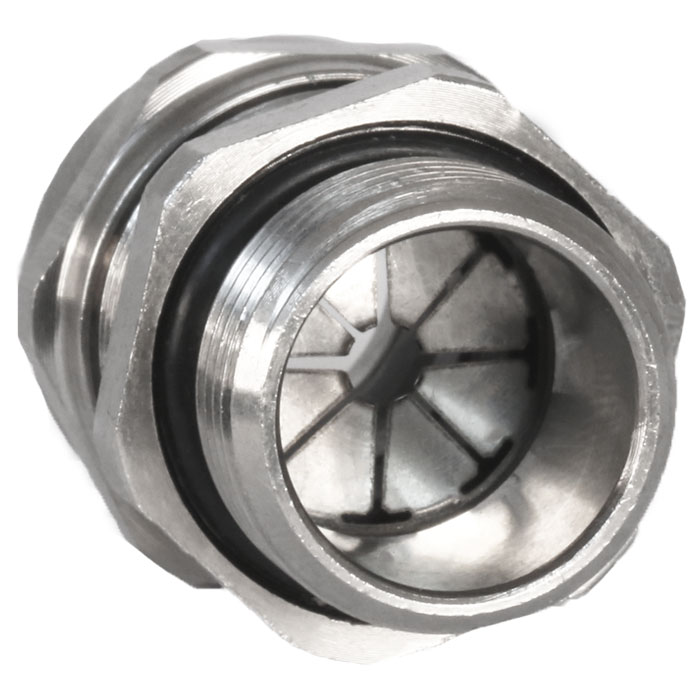
- TSZe EMC Ex | Ex eb, Ex ta | Strain Relief Metal Cable Gland
- Ex ta
-
IP66, 67, 68, 69K
-
+105°C to -60°C
TSZe EMC Ex | Ex eb, Ex ta | Strain Relief Metal Cable Gland For all Types of Braided / Screened Cables
We'd like to keep in touch
We have some exciting things in the pipeline - if you'd like to be the first to know please enter your email address below.
The TSZ Ex range of strain relief metal cable glands are designed for superior EMC performance and suitable for use in industrial (safe) areas with all types of braided cables, and have a temperature rating of +105°c to -60°c.
With 360° earth contact around cable braid circumference, the TSZe can be used with confidence where an earth connection is required.
The TSZ Ex range meets the requirements of well-known cable gland standards including EN 62444 and IEC 62444.
For more specific applications IP68 & IP69X ingress discs or plugs are available.
- Designed for superior EMC performance
- 360° contact around screen circumference
- Third party EMC performance tested to EN 55032
- Approved to the latest editions of IEC/EN 60079
- Internationally marked IECEx, ATEX and UKEX
- Suitable for intrinsically safe (Ex i) circuits
- Unique strain relief sealing system
- Third party certified to IEC/EN 62444
- Widest cable range take on the market
- O-ring interface seal included as standard
- Transit disc or IP68, IP69 and IP69K rated IP plug options available
- Product supplied in nickel-plated brass, or stainless steel on request
| Design Specification | IEC 62444, EN 62444 (EN Metric only) |
| Mechanical Classifications* | Impact = Level 6, Cable Anchorage = Type A |
| Enclosure Protection | IK08 to IEC 62262 (7 joules) |
| Ingress Protection Rating ** | IP66, IP67, IP68**, IP69 and IP69K |
| Cable Gland Material | Nickel-plated brass, Stainless Steel (option) |
| Seal Material | CMP SOLO LSF Halogen-free Thermoset Elastomer |
| Cable Type | Screened or Braided |
| Sealing Technique | CMP unique strain relief sealing system |
| Sealing Area(s) | Cable Outer Sheath |
| ATEX Certificate | CML 19ATEX3185X |
| UKEX Certificate | CML 21UKEX3264X |
| Code of Protection | II 2G 1D, Ex eb IIC Gb, Ex ta IIIC Da |
| Compliance Standards | EN 60079-0,7,31 |
| EAC Certificate | EAC KZ 7100841.01.01.07867 |
| SANS | IA S-XPL21804 21.0014X |
| IECEx Certificate | IECEx CML 19.0062X |
| Code of Protection | Ex eb IIC Gb, Ex ta IIIC Da |
| Compliance Standards | IEC 60079-0,7,31 |
| CCC Certificate | 2020322313003450 |
| INMETRO Certificate | TÜV 25.0780X |
| UkrSEPRO | CЦ 25.1098Х |
| PESO | Ex e: P533772 |
* Mechanical classifications applied as per IEC/EN 62444
** IP68 tested to 300 kPa for 16 hours (equivalent to 30 metres water depth)
Certificates


Click here to view how to order
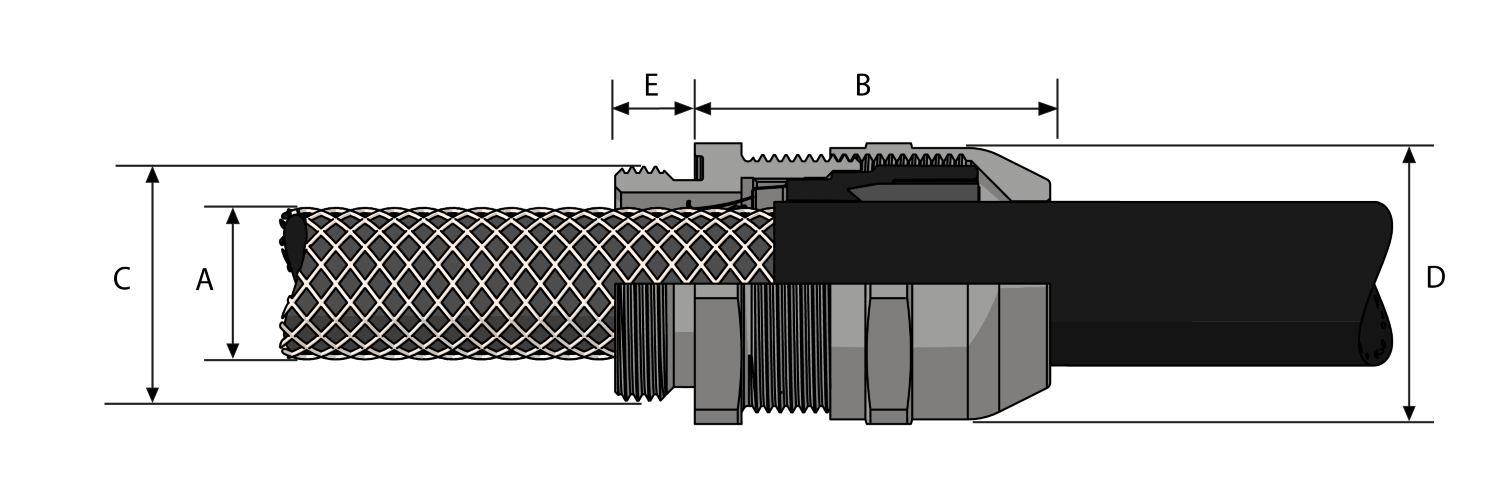
| DUAL SEAL | AVAILABLE ENTRY THREADS 'C' | OVERALL CABLE DIAMETER 'A' | ACROSS FLATS 'D' | ACROSS CORNERS 'D' | PROTRUSION LENGTH 'B' | WEIGHT GLAND ONLY † (KG) | ||||||
| STANDARD | OPTION | |||||||||||
| CABLE GLAND ONLY | CABLE GLAND WITH LOCKNUT | METRIC | THREAD LENGTH (METRIC) 'E' | LONG THREAD LENGTH (METRIC) 'E' | NPT | THREAD LENGTH (NPT) 'E' | MIN | MAX | MAX | MAX | ||
| 16DTSZE1TA5 | 16DTSZE2TN5 | M16 | 6.0 | 12.0 | 3⁄8” | 11.0 | 3.0 | 10.0 | 20.0 | 22.0 | 23.6 | 0.033 |
| 20DTSZE1TA5 | 20DTSZE2TN5 | M20 | 6.5 | 12.0 | 1⁄2” | 14.0 | 5.0 | 14.0 | 24.0 | 26.4 | 26.7 | 0.046 |
| 25DTSZE1TA5 | 25DTSZE2TN5 | M25 | 7.0 | 12.0 | 3⁄4” | 15.0 | 9.0 | 18.0 | 30.0 | 33.0 | 32.0 | 0.081 |
| 32DTSZE1TA5 | 32DTSZE2TN5 | M32 | 8.0 | 12.0 | 1” | 18.0 | 12.5 | 25.0 | 39.0 | 42.9 | 37.8 | 0.134 |
| 40DTSZE1TA5 | 40DTSZE2TN5 | M40 | 8.0 | 15.0 | 1 1⁄4” | 18.0 | 19.0 | 32.0 | 50.0 | 55.0 | 44.7 | 0.252 |
| 50DTSZE1TA5 | 50DTSZE2TN5 | M50 | 9.0 | 15.0 | 1 1⁄2” | 19.0 | 22.0 | 38.0 | 57.0 | 62.7 | 48.7 | 0.347 |
| 63DTSZE1TA5 | 63DTSZE2TN5 | M63 | 10.0 | 15.0 | 2” | 20.0 | 28.0 | 48.0 | 68.0 | 74.8 | 52.2 | 0.503 |
| STANDARD SEAL | AVAILABLE ENTRY THREADS 'C' | OVERALL CABLE DIAMETER 'A' | ACROSS FLATS 'D' | ACROSS CORNERS 'D' | PROTRUSION LENGTH 'B' | WEIGHT GLAND ONLY † (KG) | ||||||
| STANDARD | OPTION | |||||||||||
| CABLE GLAND ONLY | CABLE GLAND WITH LOCKNUT | METRIC | THREAD LENGTH (METRIC) 'E' | LONG THREAD LENGTH (METRIC) 'E' | NPT | THREAD LENGTH (NPT) 'E' | MIN | MAX | MAX | MAX | ||
| 12TSZE1TA5 | 12TSZE2TN5 | M12 | 6.0 | 12.0 | 1⁄4” | 11.0 | 3.0 | 6.5 | 16.0 | 17.6 | 22.3 | 0.020 |
| 16STSZE1TA5 | 16STSZE2TN5 | M16 | 6.0 | 12.0 | 3⁄8” | 11.0 | 3.0 | 7.0 | 20.0 | 22.0 | 23.6 | 0.032 |
| 16TSZE1TA5 | 16TSZE2TN5 | M16 | 6.0 | 12.0 | 3⁄8” | 11.0 | 6.0 | 10.0 | 20.0 | 22.0 | 23.6 | 0.032 |
| 20STSZE1TA5 | 20STSZE2TN5 | M20 | 6.5 | 12.0 | 1⁄2” | 14.0 | 5.0 | 10.0 | 24.0 | 26.4 | 26.7 | 0.046 |
| 20TSZE1TA5 | 20TSZE2TN5 | M20 | 6.5 | 12.0 | 1⁄2” | 14.0 | 9.0 | 14.0 | 24.0 | 26.4 | 26.7 | 0.045 |
| 25STSZE1TA5 | 25STSZE2TN5 | M25 | 7.0 | 12.0 | 3⁄4” | 15.0 | 9.0 | 15.5 | 30.0 | 33.0 | 32.0 | 0.081 |
| 25TSZE1TA5 | 25TSZE2TN5 | M25 | 7.0 | 12.0 | 3⁄4” | 15.0 | 12.5 | 18.0 | 30.0 | 33.0 | 32.0 | 0.080 |
| 32STSZE1TA5 | 32STSZE2TN5 | M32 | 8.0 | 12.0 | 1” | 18.0 | 12.5 | 19.0 | 39.0 | 42.9 | 37.8 | 0.133 |
| 32TSZE1TA5 | 32TSZE2TN5 | M32 | 8.0 | 12.0 | 1” | 18.0 | 17.0 | 25.0 | 39.0 | 42.9 | 37.8 | 0.130 |
| 40STSZE1TA5 | 40STSZE2TN5 | M40 | 8.0 | 15.0 | 1 1⁄4” | 18.0 | 19.0 | 27.0 | 50.0 | 55.0 | 44.7 | 0.251 |
| 40TSZE1TA5 | 40TSZE2TN5 | M40 | 8.0 | 15.0 | 1 1⁄4” | 18.0 | 24.0 | 32.0 | 50.0 | 55.0 | 44.7 | 0.250 |
| 50STSZE1TA5 | 50STSZE2TN5 | M50 | 9.0 | 15.0 | 1 1⁄2” | 19.0 | 22.0 | 32.0 | 57.0 | 62.7 | 48.7 | 0.346 |
| 50TSZE1TA5 | 50TSZE2TN5 | M50 | 9.0 | 15.0 | 1 1⁄2” | 19.0 | 28.0 | 38.0 | 57.0 | 62.7 | 48.7 | 0.340 |
| 63STSZE1TA5 | 63STSZE2TN5 | M63 | 10.0 | 15.0 | 2” | 20.0 | 28.0 | 39.0 | 68.0 | 74.8 | 52.2 | 0.501 |
| 63TSZE1TA5 | 63TSZE2TN5 | M63 | 10.0 | 15.0 | 2” | 20.0 | 37.0 | 48.0 | 68.0 | 74.8 | 52.2 | 0.489 |
| Part numbers in table are for standard. For guidance ordering alternate materials or alternate thread types, please contact your CMP sales representative. | ||||||||||||
| † Weight displayed for standard metric entry thread only | ||||||||||||
| For MOQ please contact CMP directly. | ||||||||||||
| Dimensions displayed in mm unless otherwise specified | ||||||||||||
Form of Protection Ex ‘e’
Increased Safety Enclosure Type ‘e’ (e.g. IEC 60079-7): Whilst explosive mixtures may enter the equipment, the enclosure is not designed to withstand an internal explosion. Instead, the likelihood of a fault condition, which could result in ignition of explosive mixtures, is significantly reduced by the following measures. The (non-incendive) components used in the equipment shall not produce arcs or sparks or dangerous temperatures in normal working conditions.
Read moreForm of Protection Ex ‘de’
Combined Flameproof Enclosure Type ‘d’ & Increased Safety Enclosure Type ‘e’ (e.g. IEC 60079-1 & IEC 60079-7): Primary Flameproof Type ‘d’ Enclosure with Secondary Increased Safety Type ‘e’ Protection, allowing reduced frequency of periodic maintenance and inspection cycle because of the ‘e’ philosophy strategically employed. In the case of Flameproof Type ‘d’ Enclosures having an Increased Safety Type ‘e’ Terminal Chamber, ‘line barriers’ would normally be utilised between the Type ‘d’ and Type ‘e’ compartments creating an indirect cable entry interface.
Read moreForm of Protection Ex ‘i’
Intrinsically Safe Enclosure / System Type ‘i’ (e.g. IEC 60079-11): Intrinsically Safe Equipment (Sub grouped into Ex ‘ia’, Ex ‘ib’, and Ex ‘ic’) incorporates circuits which, due to their low spark energy potential, are not capable of igniting an explosive mixture. Ex ‘ib’ equipment is designed to be safe under one fault condition and can be used in Zone 1 explosive atmospheres. Ex ‘ia’ equipment is designed to be safe under two fault conditions and can be used in Zone 0 explosive atmospheres. Ex ‘ic’ equipment is designed to be safe in normal operation, without any faults, and can be used only in Zone 2 explosive atmospheres. The recent introduction of Ex ‘ic’, according to IEC 60079-11, for Zone 2 applications co-incides with the removal of protection method ‘nL’ from IEC 60079-15.
Read moreVisit our Knowledge Base for technical expertise and advice, gathered over CMP's 60+ years' experience in the art of terminating cable glands.
Sign up now