Short Circuit Testing
CMP Products Texas Inc. has carried out over 300 short circuit tests in accordance with the IEC 61914 standard ‘cable cleats for electrical installations’. These tests include various peak faults, cable cleat spacing intervals, and cable formations to conclusively prove the cable cleats’ ability to withstand and resist a range of electromechanical forces according to IEC 61914. CMP Products Texas Inc. has the technical resources, capabilities and capacity to engage with its clients and deliver bespoke solutions to suit new or unusual situations. The company is able to conduct physical short circuit tests on any of its cable cleats for project specific applications including: specific cable size / type, fault current, cable cleat, and fixing centre / spacing interval configurations.
Test for resistance to electromechanical force according to IEC 61914
A short circuit test is carried out as follows, using the manufacturer’s or responsible vendor’s declared values of peak short circuit current (ip) and initial r.m.s symmetrical short circuit current (I”k). Where there are a number of cable cleats in the range, one or more classes are
defined (see IEC 61914 – Clause 5.1). This test is performed on the most critical size in each class.
The test is carried out at ambient temperature, considered to be the defined temperature for permanent application, using unarmored single core 600 V / 1,000 V cable with stranded copper conductor. A test rig is assembled using the selected cables and cable cleats, being the equipment under test, with the equipment and cables used being fully documented. The test is then carried out on the declared arrangement at the declared short circuit level.
Typical layout for testing for the resistance to electromechanical forces during short circuit:
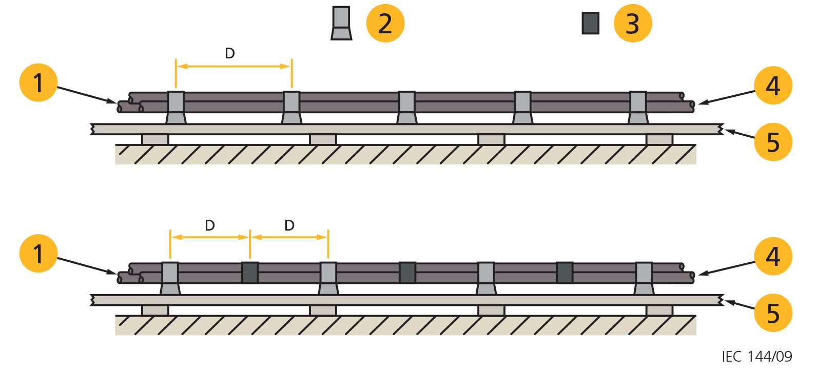
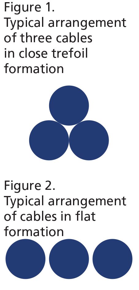
For the purpose of testing, the arrangement of the cables may be as shown in Figure 1, Figure 2 or any other configuration as declared by the manufacturer or responsible vendor.
One end of the test set-up is connected to a three phase supply and the other end to a short circuiting busbar, with all three phases connected. The cable is restrained at a minimum of 5 positions along the length of the cable run. Where intermediate restraints are used, at least 4
cable cleats and at least 3 intermediate restraints shall be used. Cable cleats and intermediate restraints, where used, shall be equally spaced. The cable cleats are fixed to a mounting surface defined by the manufacturer (e.g. cable ladder) which shall be suitably selected taking into account the electromechanical forces likely to occur during the test.
Care is taken to ensure that the cross-sectional area of the cable is adequate for the magnitude and duration of the test current.
The manufacturer’s or responsible vendor’s catalog references of the cable cleats and intermediate restraint (where used), the assembly details showing the spacing intervals and the external cable diameter used in the test shall be recorded.
The test set-up is subjected to a three phase short circuit for a duration of not less than 0.1 s. The duration of the test is recorded along with any other relevant data.
IEC 61914 CLAUSE 9.5.2 FOR CABLE CLEATS AND INTERMEDIATE RESTRAINTS CLASSIFIED IN IEC 61914:2009 CLAUSE 6.4.3 / IEC 61914:2015 CLAUSE 6.4.4
(IEC 61914:2009 Clause 6.4.3 / IEC 61914:2015 Clause 6.4.4 Resistant to electromechanical forces, withstanding one short circuit)
Cable cleats and intermediate restraints classified under the aforementioned clauses shall comply with the following requirements:
- there shall be no failure that will affect the intended function of holding the cables in place;
- the cable cleats and the intermediate restraints, if used, shall be intact with no missing parts (minor deformation is acceptable):
- there shall be no cuts or damage visible to normal or corrected vision to the outer sheath of the cable caused by the cable cleats or by the intermediate restraints, if used.
IEC 61914 CLAUSE 9.5.3 FOR CABLE CLEATS AND INTERMEDIATE RESTRAINTS CLASSIFIED IN IN IEC 61914:2009 CLAUSE 6.4.4 / IEC 61914:2015 CLAUSE 6.4.5
(IEC 61914:2009 Clause 6.4.4 / IEC 61914:2015 Clause 6.4.5 Resistant to electromechanical forces, withstanding more than one short circuit)
Cable cleats and intermediate restraints classified under the aforementioned clauses shall comply with Clause 9.5.2. After a second short circuit application, a voltage withstand test is performed by applying a minimum test voltage of 2.8 kV d.c. for a period of (60+5 –0) seconds according to the provisions of IEC 60060-1:1989, ‘High-voltage test techniques – Part 1: General definitions and test requirements’, Clause 13.1, ‘Requirements for the test voltage’, and Clause 14.1, ‘Withstand voltage tests’. The voltage withstand test shall be administered between the cable cores and the mounting frame. The mounting frame shall be bonded to the earthing system. Where the cables incorporate screening or shielding, the screens and shields shall be bonded together and also bonded to the mounting frame. Where the cables do not incorporate screening or shielding, the cable jackets or sheaths and mounting frames shall be pre-wetted with sufficient water to facilitate a current leakage path along the outer jackets or sheaths. The cable jackets or sheaths and mounting frames shall be pre-wetted for (2+1–0) minutes before the test begins using water with a resistivity of (100+15–15 )?.m, which shall be measured immediately before starting the test.
The cables shall meet the requirements of the voltage withstand test without failure of the insulation.
CALCULATION OF FORCES CAUSED BY SHORT CIRCUIT CURRENTS (IEC 61914)
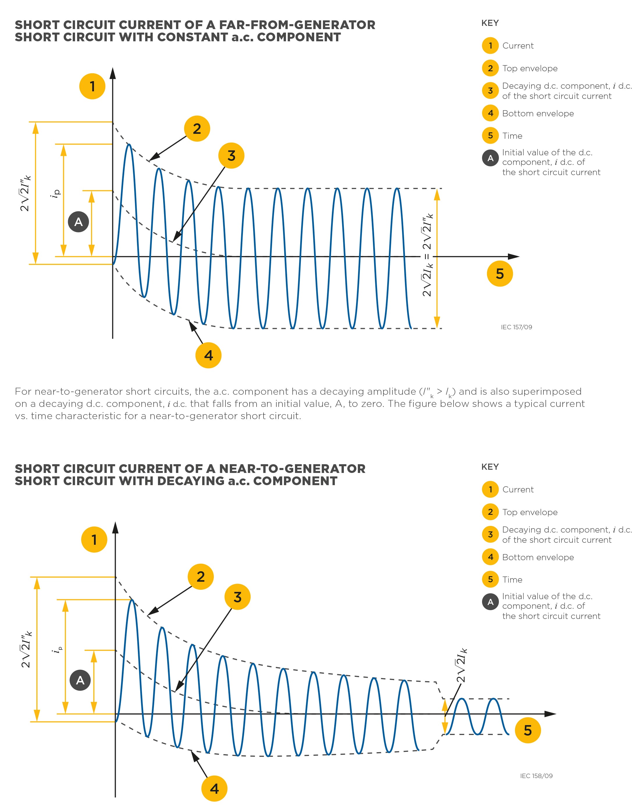
The characteristics of the current during a short circuit depend on a number of factors, including the electrical separation from the generator. The figure below shows a current vs. time characteristic typical of a far-from-generator short circuit. The a.c. component in this case has a constant amplitude (I”k = Ik) and is superimposed on a decaying d.c component, i d.c. This falls from an initial value, A, to zero.
SPECIFICATION OF THE TEST CURRENT
A complete specification of short circuit currents should give the currents as a function of time at the short circuit location from the initiation of the short circuit up to its end. In most practical cases, this is not necessary. It is usually sufficient to know the peak current, ip, and the values of the initial r.m.s symmetrical, I”k, and steady state, Ik, currents.
In order to specify the current used in a short circuit test the following are quoted:
- the peak current, ip;
- the initial r.m.s symmetrical short circuit current, I”k;
- the short circuit duration, t.
CALCULATION OF THE MECHANICAL FORCES BETWEEN CONDUCTORS
The electromagnetic force acting on a conductor is determined by the current in the conductor and the magnetic field from the neighbouring conductors. In cable installations, the distances between the conductors are normally small and hence the forces may be considerable. In the case of two parallel conductors, the electromagnetic force on a conductor can be derived from Equation B1:
F(t) = B(t) · i(t) · l
- l is the length;
- F(t) is the momentary electromagnetic force on a conductor;
- B(t) is the momentary magnetic field from the neighbouring conductor;
- i(t) is the momentary current in the neighbouring conductor.
If the d.c. component of the short circuit current is disregarded, the momentary force has a sinusoidal variation with a frequency twice the frequency of the currents (Equation B.1). The d.c. component gives a decaying force-component with a frequency the same as the system frequency.
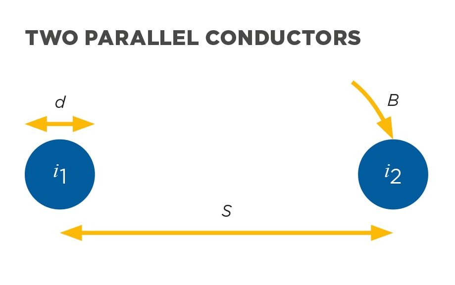
For the two parallel conductors in figure above, the magnetic field from current i1, at the location of the other conductor is:
B = ?0 · H = ?0 · i1 / 2 ·? · S (B.2)
where ?o = 4·?·10–7 (H/m)
and the mechanical force is:
F = i2 × B = i2 ·?0 · i1 / 2·? · S (B.3)
his equation is usually written as:
Fs = 0.2 · i1 · i2 / S (B.4)
In this equation, the force is given in N/m, i in kA and S in metres. The evaluation of Equation B.4 requires S >> d but gives an acceptable accuracy when the current distribution is uniform (or symmetrical) within the conductors.
The vector Equation B.3 confirms that two parallel conductors are repelled if the two currents have a difference in phase angle of 180° and that the force is directed towards the other conductor for currents that have the same phase angle.
In a three phase system, the magnetic field in Equation B.2 is the resulting momentary vector value from the other two phases.
For a three phase short circuit with the conductors in flat configuration, the forces on the two outer conductors are always directed outwards from the central conductor. The force on the central conductor is oscillating. The maximum force on the outer conductors in flat formation can be calculated by:
Fƒo = 0.16 ip2 / S (B.5)
The maximum force on the middle conductor in flat formation can be calculated by:
Fƒm = 0.17 ip2 / S (B.6)
For a three phase short circuit with the cables in a trefoil configuration the maximum force on the conductor is:
Ft = 0.17 ip2 / S (B.7)
where:
Fs is the maximum force on the cable conductor in flat formation for a single phase short circuit [N/m];
Fƒo is the maximum force on the outer cable conductors in flat formation for a three phase short circuit [N/m];
Fƒm is the maximum force on the centre cable conductor in flat formation for a three phase short circuit [N/m];
Ft is the maximum force on the cable conductor in a trefoil configuration for a three phase short circuit [N/m];
ip is the peak short circuit current [kA];
d is the external diameter of the conductor [m];
S is the centre to centre distance between two neighbouring conductors [m].
