- Home
- Cable Glands
- Products
- Group I Mining
- PX2KW/MF | Ex eb, Ex db | Explosive Atmosphere Barrier Cable Gland
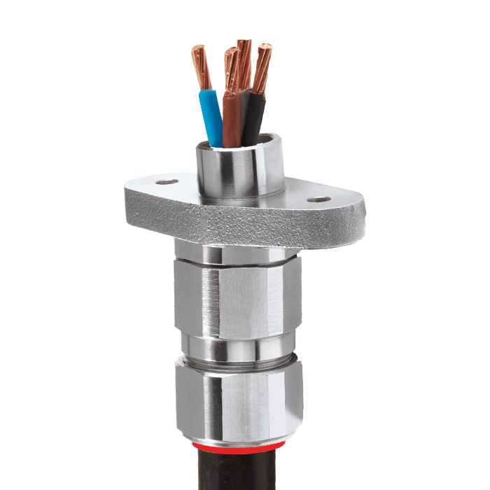
PX2KW/MF | Ex eb, Ex db | Explosive Atmosphere Barrier Cable Gland For all types Steel & Aluminium Wire Armoured cables
We'd like to keep in touch
We have some exciting things in the pipeline - if you'd like to be the first to know please enter your email address below.
Mining, Internationally Approved, Flanged Explosive Atmosphere Barrier Cable Gland
• Complete with flanged adaptor
• Metal-to-metal armour clamping
• Direct & remote installation
• Compound barrier type flameproof seal
• Controlled outer ‘load retention’ seal
• Unique OSTG prevents overtightening
• -60°C to +85°C
• Permitted in Zone 1
• Internationally marked, IECEx & ATEX
• Superior EMC performance
• Compound barrier seals around internal cable cores after removing any inner cable sheath/bedding; completely eliminating any risk of coldflow.
Note: See MA/FT, MA/B page for flange mounting dimensions
Alternative flange sizes available upon request
Also available with RapidEx
For under / oversized armour wires click here
| Design Specification | BS 6121:Part 1:1989, IEC 62444, EN 62444 |
| Mechanical Classifications* | Impact = Level 8, Retention = Class D |
| Enclosure Protection | IK10 to IEC 62262 (20 joules) Brass & Stainless Steel only |
| Electrical Classifications* | Category B |
| ATEX Certificate | CML 18ATEX1325X, CML 18ATEX1332U |
| Code of Protection | IM2 Ex db I Mb |
| Compliance Standards | EN 60079-0,1,7 |
| IECEx Certificate | IECEx CML 18.0182X, IECEx CML 18.0189U |
| UkrSEPRO | CU 19.0371X |
| Code of Protection | Ex db I Mb |
| Compliance Standards | IEC 60079-0,1,7 |
| CCOE / PESO (India) Certificate | P444949 |
| Ingress Protection Rating ** | IP66 |
| Cable Gland Material | Brass, Electroless Nickel Plated Brass, Stainless Steel |
| Seal Material | CMP SOLO LSF Halogen Free Thermoset Elastomer / Epoxy Barrier Compound |
| Cable Type | Single Wire Armour (SWA), Aluminium Wire Armour (AWA) |
| Armour Clamping | Detachable Armour Cone & AnyWay Universal Clamping Ring |
| Sealing Technique | Unique CMP ‘LRS’ Outer Seal (Load Retention Seal) |
| Sealing Area(s) | Inner Compound Barrier & Outer Sheath |
| Optional Accessories | Locknuts, Earth Tags, Serrated Washers, Entry Thread Seals, Shrouds,Ingress Discs |
| Optional Installation Tools | Spanners, Armour Former Tool |
Note : * Mechanical & Electrical Classifications applied as per IEC 62444 & EN 62444
** Refer to Maintaining a Seal for further information on Ingress Protection Ratings
Certificates


Product Selection Table
Click here to view how to order
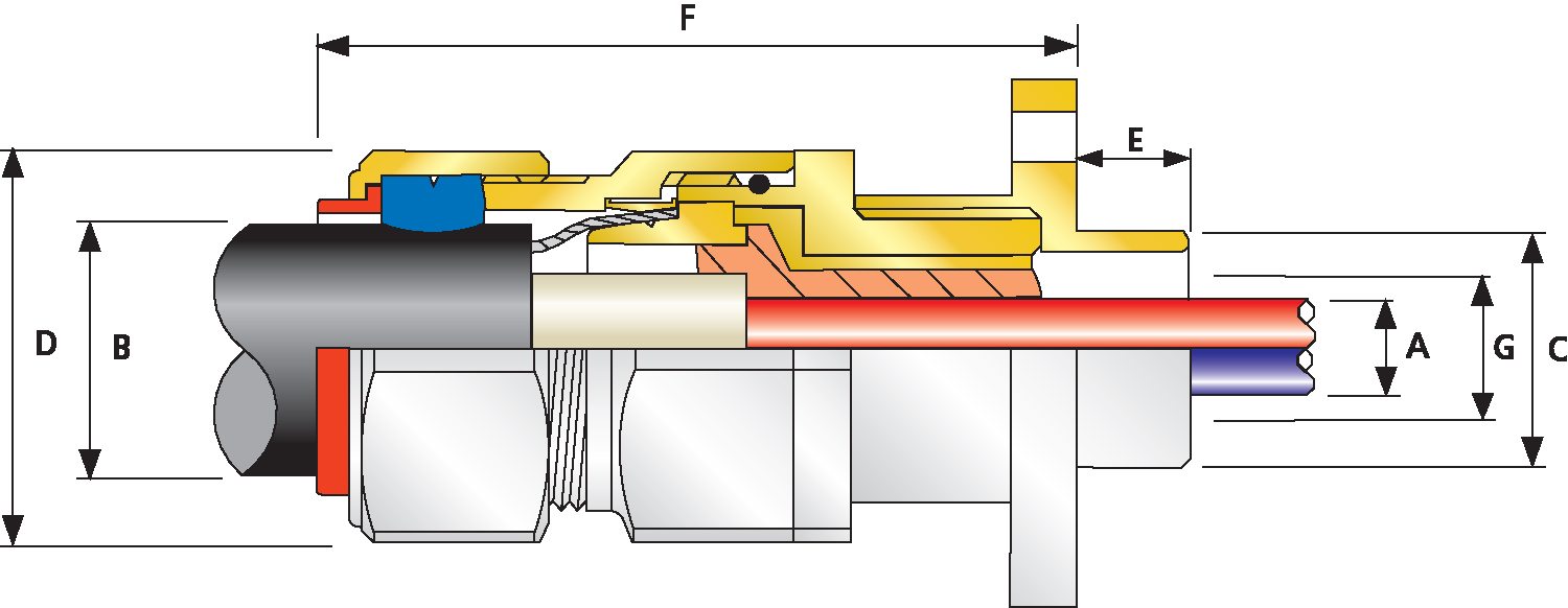
| Cable Gland Size | Minimum Spigot Length "E" | Spigot Diameter "C" | Maximum Number of Cores | Maximum Diameter over Conductors "A" | Cable Bedding Diameter "G" | Overall Cable Diameter 'B' | Pliable Armour Wire | Across Flats 'D' | Across Corners 'D' | Protrusion Length 'F' | Combined Ordering Reference (*Brass Metric) | Cable Gland Weight (Ozs) |
||||
| Max | Cores | Max | Min | Max | Min | Max | Max | Max | Size | Type | Ordering Suffix |
|||||
| 20S | 0.59 | 0.75 | 11 | 0.46 | 0.46 | 0.37 | 0.63 | 0.03 | 0.05 | 1.20 | 1.32 | 3.11 | 20S | PX2KW | 1RA/MF | 13.76 |
| 20 | 0.59 | 0.75 | 11 | 0.50 | 0.51 | 0.49 | 0.82 | 0.03 | 0.05 | 1.20 | 1.32 | 3.15 | 20 | PX2KW | 1RA/MF | 14.11 |
| 25S | 0.59 | 1.00 | 21 | 0.69 | 0.70 | 0.55 | 0.87 | 0.05 | 0.06 | 1.48 | 1.63 | 3.55 | 25S | PX2KW | 1RA/MF | 21.87 |
| 25 | 0.59 | 1.00 | 21 | 0.69 | 0.70 | 0.72 | 1.03 | 0.05 | 0.06 | 1.48 | 1.63 | 3.55 | 25 | PX2KW | 1RA/MF | 21.87 |
| 32 | 0.59 | 1.25 | 38 | 0.93 | 0.94 | 0.93 | 1.33 | 0.06 | 0.08 | 1.81 | 1.99 | 3.79 | 32 | PX2KW | 1RA/MF | 31.39 |
| 40 | 0.59 | 1.50 | 59 | 1.18 | 1.19 | 1.10 | 1.59 | 0.06 | 0.08 | 2.17 | 2.38 | 4.04 | 40 | PX2KW | 1RA/MF | 41.98 |
| 50S | 0.59 | 2.00 | 89 | 1.44 | 1.45 | 1.39 | 1.84 | 0.08 | 0.10 | 2.36 | 2.60 | 4.20 | 50S | PX2KW | 1RA/MF | 57.85 |
| 50 | 0.59 | 2.00 | 89 | 1.61 | 1.63 | 1.59 | 2.09 | 0.08 | 0.10 | 2.76 | 3.04 | 4.20 | 50 | PX2KW | 1RA/MF | 68.08 |
| 63S | 0.59 | 2.50 | 115 | 1.89 | 1.91 | 1.80 | 2.34 | 0.08 | 0.10 | 2.95 | 3.25 | 3.98 | 63S | PX2KW | 1RA/MF | 76.19 |
| 63 | 0.59 | 2.50 | 115 | 2.11 | 2.13 | 2.15 | 2.59 | 0.08 | 0.10 | 3.15 | 3.46 | 3.91 | 63 | PX2KW | 1RA/MF | 78.31 |
| 75S | 0.59 | 3.00 | 140 | 2.36 | 2.37 | 2.32 | 2.83 | 0.08 | 0.10 | 3.54 | 3.90 | 4.50 | 75S | PX2KW | 1RA/MF | 128.75 |
| 75 | 0.59 | 3.00 | 140 | 2.53 | 2.53 | 2.63 | 3.09 | 0.10 | 0.12 | 3.90 | 3.94 | 4.56 | 75 | PX2KW | 1RA/MF | 144.62 |
| Dimensions displayed in inches unless otherwise stated | ||||||||||||||||
| Cable Gland Size | Minimum Spigot Length "E" | Spigot Diameter "C" | Maximum Number of Cores | Maximum Diameter over Conductors "A" | Cable Bedding Diameter "G" | Overall Cable Diameter 'B' | Pliable Armour Wire | Across Flats 'D' | Across Corners 'D' | Protrusion Length 'F' | Combined Ordering Reference (*Brass Metric) | Cable Gland Weight (Kgs) |
||||
| Max | Cores | Max | Min | Max | Min | Max | Max | Max | Size | Type | Ordering Suffix |
|||||
| 20S | 15.0 | 19.0 | 11 | 11.7 | 11.7 | 9.5 | 15.9 | 0.8 | 1.25 | 30.5 | 33.6 | 79.1 | 20S | PX2KW | 1RA/MF | 0.39 |
| 20 | 15.0 | 19.0 | 11 | 12.6 | 12.9 | 12.5 | 20.9 | 0.8 | 1.25 | 30.5 | 33.6 | 80.1 | 20 | PX2KW | 1RA/MF | 0.40 |
| 25S | 15.0 | 25.4 | 21 | 17.5 | 17.9 | 14.0 | 22.0 | 1.25 | 1.6 | 37.5 | 41.3 | 90.1 | 25S | PX2KW | 1RA/MF | 0.62 |
| 25 | 15.0 | 25.4 | 21 | 17.5 | 17.9 | 18.2 | 26.2 | 1.25 | 1.6 | 37.5 | 41.3 | 90.1 | 25 | PX2KW | 1RA/MF | 0.62 |
| 32 | 15.0 | 31.8 | 38 | 23.6 | 23.9 | 23.7 | 33.9 | 1.6 | 2.0 | 46.0 | 50.6 | 96.2 | 32 | PX2KW | 1RA/MF | 0.89 |
| 40 | 15.0 | 38.1 | 59 | 30.0 | 30.3 | 27.9 | 40.4 | 1.6 | 2.0 | 55.0 | 60.5 | 102.7 | 40 | PX2KW | 1RA/MF | 1.19 |
| 50S | 15.0 | 50.8 | 89 | 36.6 | 36.9 | 35.2 | 46.7 | 2.0 | 2.5 | 60.0 | 66.0 | 106.7 | 50S | PX2KW | 1RA/MF | 1.64 |
| 50 | 15.0 | 50.8 | 89 | 41.0 | 41.3 | 40.4 | 53.0 | 2.0 | 2.5 | 70.1 | 77.1 | 106.7 | 50 | PX2KW | 1RA/MF | 1.93 |
| 63S | 15.0 | 63.5 | 115 | 47.9 | 48.4 | 45.6 | 59.4 | 2.0 | 2.5 | 75.0 | 82.5 | 101.2 | 63S | PX2KW | 1RA/MF | 2.16 |
| 63 | 15.0 | 63.5 | 115 | 53.7 | 54.0 | 54.6 | 65.8 | 2.0 | 2.5 | 80.0 | 88.0 | 99.3 | 63 | PX2KW | 1RA/MF | 2.22 |
| 75S | 15.0 | 76.2 | 140 | 59.9 | 60.2 | 59.0 | 72.0 | 2.0 | 2.5 | 90.0 | 99.0 | 114.3 | 75S | PX2KW | 1RA/MF | 3.65 |
| 75 | 15.0 | 76.2 | 140 | 64.2 | 64.2 | 66.7 | 78.4 | 2.5 | 3.0 | 99.0 | 100.0 | 115.8 | 75 | PX2KW | 1RA/MF | 4.10 |
| Dimensions displayed in millimeters unless otherwise stated | ||||||||||||||||
Protection by Enclosure Against Mechanical Impact
It is critically important that enclosures afford a level of mechanical protection relevant to the area of installation that provides optimum electrical and operational safety. The international standard IEC 62262 covering ‘Degrees of protection provided by enclosures for electrical equipment against external mechanical impacts (IK Code)’ outlines the requirements for testing and rating of enclosures of different materials, so that careful selection to suit the application can be achieved.
Read moreVisit our Knowledge Base for technical expertise and advice, gathered over CMP's 60+ years' experience in the art of terminating cable glands.
Sign up now