- Home
- Cable Glands
- Products
- Explosive Atmosphere
- CXe | Ex eb, Ex ta | Explosive Atmosphere Cable Gland
- Ex ta
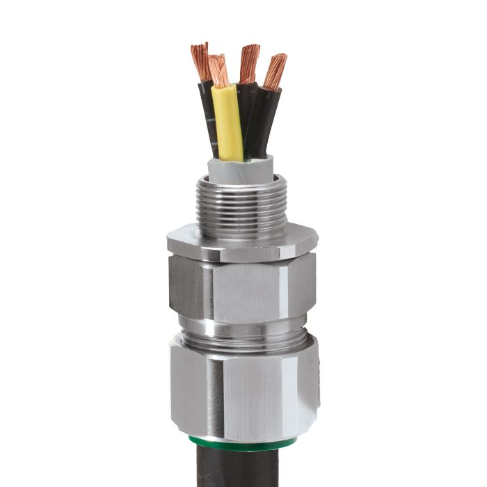
CXe | Ex eb, Ex ta | Explosive Atmosphere Cable Gland For Braid & Steel Tape Armoured Cables
We'd like to keep in touch
We have some exciting things in the pipeline - if you'd like to be the first to know please enter your email address below.
Internationally Approved, Ex e, Explosive Atmosphere Cable Gland
• Metal-to-metal armour clamping
• Direct & remote installation
• Permanently crimped, low impedance earth termination
• Secure against self-loosening
• Controlled outer ‘load retention’ seal
• Unique OSTG prevents overtightening
• -60°C to +130°C
• Internationally marked, IECEx & ATEX
• EMC tested
| Design Specification | BS 6121:Part 1:1989, IEC 62444, EN 62444 |
| Mechanical Classifications* | Impact = Level 8, Retention = Class D |
| Enclosure Protection | IK10 to IEC 62262 (20 joules) Brass & Stainless Steel only |
| Electrical Classifications * | Category B (Category A when used with braid, tape or pliable wire armour cables) |
| ATEX Certificate | CML 18ATEX1323X |
| UKEX Certificate | CML 21UKEX1251X |
| Code of Protection | II 2G, II 1D, Ex eb IIC Gb, Ex ta IIIC Da |
| Compliance Standards | EN 60079-0,7,31 |
| IECEx Certificate | IECEx CML 18.0180X |
| Code of Protection | Ex eb IIC Gb, Ex ta IIIC Da |
| Compliance Standards | IEC 60079-0,7,31 |
| EAC Certificate | C-GB.A07.B.04594/22 |
| CCC Certificate | 2020322313003285 |
| INMETRO Approval | TÜV 12.0617X |
| CCOE / PESO (India) Certificate | Ex nR: P548695, Ex e: P533772 |
| RETIE Approval | 03866 |
| UkrSEPRO | CU 19.0371X |
| SANS | IA S-XPL21804 21.0009X |
| Marine Approvals | LRS: 01/00172, DNV: TAE00000Y, ABS: 21-2090433-PDA, BV: 43180 |
| Ingress Protection Rating ** | IP66 as standard (IP67, IP68 available upon request) |
| Cable Gland Material | Brass, Electroless Nickel Plated Brass, Aluminium, Stainless Steel |
| Seal Material | CMP SOLO LSF Halogen Free Thermoset Elastomer |
| Cable Type | Wire Braid Armour (e.g. SWB), Screened Flexible (EMC) Wire Braid (e.g. CY / SY), Pliable Wire Armour (PWA), Steel Tape Armour (STA), Strip Armour (e.g. ASA) |
| Armour Clamping | Detachable Armour Cone & AnyWay Universal Clamping Ring |
| Sealing Technique | Unique CMP ‘LRS’ Outer Seal (Load Retention Seal) |
| Sealing Area(s) | Cable Outer Sheath |
| Optional Accessories | Locknuts, Earth Tags, Serrated Washers, Entry Thread Seals, Shrouds,Ingress Discs |
| Optional Installation Tools | Spanners |
| ECAS Certificate | E23-02-065457 |
Note: * Mechanical & Electrical Classifications applied as per IEC 62444 & EN 62444
** When CMP installation accessories are used. Refer to Maintaining a Seal for further information.
*** IP68 tested to a minimum depth of 30 metres for 12 hours, alternate depths / durations can be provided upon request
Certificates


Product Selection Table
Click here to view how to order
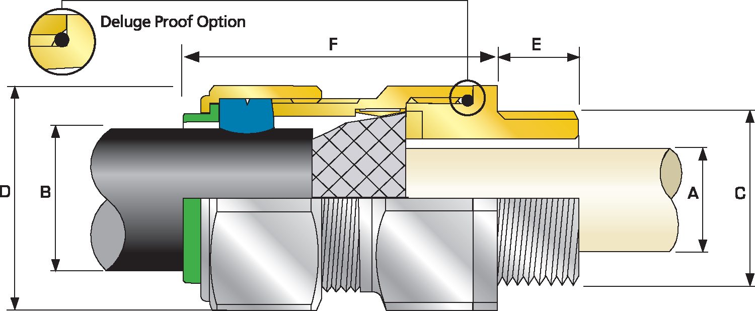
| Cable Gland Size | Available Entry Threads 'C' (Alternate Metric Thread Lengths Available) | Cable Bedding Diameter 'A' | Overall Cable Diameter 'B' | Armour Range Grooved Cone (X) | Across Flats 'D' | Across Corners 'D' | Protrusion Length 'F' | Combined Ordering Reference (*Brass Metric) | Shroud | Cable Gland Weight (Kgs) |
|||||
| Metric | Thread Length (Metric) 'E' | Max | Max | Max | Min | Max | Max | Max | Size | Type | Ordering Suffix |
||||
| 20S16 | M20 | 0.59 | 0.34 | 0.24 | 0.52 | 0.01 | 0.04 | 0.94 | 1.04 | 1.89 | 20S16 | CXE | 1RA | PVC04 | 3.53 |
| 20S | M20 | 0.59 | 0.46 | 0.37 | 0.63 | 0.01 | 0.04 | 0.94 | 1.04 | 1.89 | 20S | CXE | 1RA | PVC04 | 3.53 |
| 20 | M20 | 0.59 | 0.55 | 0.49 | 0.82 | 0.02 | 0.04 | 1.20 | 1.32 | 1.89 | 20 | CXE | 1RA | PVC06 | 5.29 |
| 25S | M25 | 0.59 | 0.79 | 0.55 | 0.87 | 0.02 | 0.05 | 1.48 | 1.63 | 2.20 | 25S | CXE | 1RA | PVC09 | 7.76 |
| 25 | M25 | 0.59 | 0.79 | 0.72 | 1.03 | 0.02 | 0.05 | 1.48 | 1.63 | 2.20 | 25 | CXE | 1RA | PVC09 | 7.76 |
| 32 | M32 | 0.59 | 1.02 | 0.93 | 1.33 | 0.02 | 0.05 | 1.81 | 1.99 | 2.13 | 32 | CXE | 1RA | PVC11 | 10.93 |
| 40 | M40 | 0.59 | 1.27 | 1.10 | 1.59 | 0.02 | 0.06 | 2.17 | 2.38 | 2.28 | 40 | CXE | 1RA | PVC15 | 15.87 |
| 50S | M50 | 0.59 | 1.50 | 1.39 | 1.84 | 0.02 | 0.06 | 2.36 | 2.60 | 2.40 | 50S | CXE | 1RA | PVC18 | 20.11 |
| 50 | M50 | 0.59 | 1.74 | 1.59 | 2.09 | 0.02 | 0.06 | 2.76 | 3.04 | 2.36 | 50 | CXE | 1RA | PVC21 | 26.46 |
| 63S | M63 | 0.59 | 1.97 | 1.80 | 2.34 | 0.02 | 0.06 | 2.95 | 3.25 | 2.91 | 63S | CXE | 1RA | PVC23 | 36.68 |
| 63 | M63 | 0.59 | 2.20 | 2.15 | 2.59 | 0.02 | 0.06 | 3.15 | 3.46 | 2.80 | 63 | CXE | 1RA | PVC25 | 35.98 |
| 75S | M75 | 0.59 | 2.44 | 2.32 | 2.83 | 0.02 | 0.06 | 3.54 | 3.90 | 3.39 | 75S | CXE | 1RA | PVC28 | 63.14 |
| 75 | M75 | 0.59 | 2.53 | 2.63 | 3.09 | 0.02 | 0.06 | 3.94 | 4.33 | 3.23 | 75 | CXE | 1RA | PVC30 | 73.72 |
| 90 | M90 | 0.94 | 3.09 | 3.00 | 3.56 | 0.03 | 0.06 | 4.50 | 4.95 | 3.74 | 90 | CXE | 1RA | PVC32 | 107.23 |
| 100 | M100 | 0.94 | 3.58 | 3.39 | 3.99 | 0.03 | 0.06 | 4.84 | 5.33 | 3.74 | 100 | CXE | 1RA | LSF33 | 110.41 |
| 115 | M115 | 0.94 | 3.86 | 4.00 | 4.34 | 0.03 | 0.06 | 5.25 | 5.78 | 4.23 | 115 | CXE | 1RA | LSF34 | 158.03 |
| 130 | M130 | 0.94 | 4.53 | 4.34 | 4.85 | 0.03 | 0.06 | 6.00 | 6.60 | 4.33 | 130 | CXE | 1RA | LSF35 | 203.53 |
| Dimensions displayed in inches unless otherwise stated | |||||||||||||||
| Cable Gland Size | Available Entry Threads 'C' (Alternate Metric Thread Lengths Available) | Cable Bedding Diameter 'A' | Overall Cable Diameter 'B' | Armour Range Grooved Cone (X) | Across Flats 'D' | Across Corners 'D' | Protrusion Length 'F' | Combined Ordering Reference (*Brass Metric) | Shroud | Cable Gland Weight (Kgs) |
|||||
| Metric | Thread Length (Metric) 'E' | Max | Max | Max | Min | Max | Max | Max | Size | Type | Ordering Suffix |
||||
| 20S16 | M20 | 15.0 | 8.7 | 6.1 | 13.1 | 0.3 | 1.0 | 24.0 | 26.4 | 48.0 | 20S16 | CXE | 1RA | PVC04 | 0.10 |
| 20S | M20 | 15.0 | 11.7 | 9.5 | 15.9 | 0.3 | 1.0 | 24.0 | 26.4 | 48.0 | 20S | CXE | 1RA | PVC04 | 0.10 |
| 20 | M20 | 15.0 | 14.0 | 12.5 | 20.9 | 0.4 | 1.0 | 30.5 | 33.6 | 48.0 | 20 | CXE | 1RA | PVC06 | 0.15 |
| 25S | M25 | 15.0 | 20.0 | 14.0 | 22.0 | 0.4 | 1.2 | 37.5 | 41.3 | 56.0 | 25S | CXE | 1RA | PVC09 | 0.22 |
| 25 | M25 | 15.0 | 20.0 | 18.2 | 26.2 | 0.4 | 1.2 | 37.5 | 41.3 | 56.0 | 25 | CXE | 1RA | PVC09 | 0.22 |
| 32 | M32 | 15.0 | 26.0 | 23.7 | 33.9 | 0.4 | 1.2 | 46.0 | 50.6 | 54.0 | 32 | CXE | 1RA | PVC11 | 0.31 |
| 40 | M40 | 15.0 | 32.2 | 27.9 | 40.4 | 0.4 | 1.6 | 55.0 | 60.5 | 58.0 | 40 | CXE | 1RA | PVC15 | 0.45 |
| 50S | M50 | 15.0 | 38.2 | 35.2 | 46.7 | 0.4 | 1.6 | 60.0 | 66.0 | 61.0 | 50S | CXE | 1RA | PVC18 | 0.57 |
| 50 | M50 | 15.0 | 44.1 | 40.4 | 53.0 | 0.6 | 1.6 | 70.1 | 77.1 | 60.0 | 50 | CXE | 1RA | PVC21 | 0.75 |
| 63S | M63 | 15.0 | 50.0 | 45.6 | 59.4 | 0.6 | 1.6 | 75.0 | 82.5 | 74.0 | 63S | CXE | 1RA | PVC23 | 1.04 |
| 63 | M63 | 15.0 | 56.0 | 54.6 | 65.8 | 0.6 | 1.6 | 80.0 | 88.0 | 71.0 | 63 | CXE | 1RA | PVC25 | 1.02 |
| 75S | M75 | 15.0 | 62.0 | 59.0 | 72.0 | 0.6 | 1.6 | 90.0 | 99.0 | 86.0 | 75S | CXE | 1RA | PVC28 | 1.79 |
| 75 | M75 | 15.0 | 64.2 | 66.7 | 78.4 | 0.6 | 1.6 | 100.0 | 110.0 | 82.0 | 75 | CXE | 1RA | PVC30 | 2.09 |
| 90 | M90 | 24.0 | 78.6 | 76.2 | 90.3 | 0.8 | 1.6 | 114.3 | 125.7 | 95.0 | 90 | CXE | 1RA | PVC32 | 3.04 |
| 100 | M100 | 24.0 | 91.0 | 86.1 | 101.4 | 0.8 | 1.6 | 123.0 | 135.3 | 95.0 | 100 | CXE | 1RA | LSF33 | 3.13 |
| 115 | M115 | 24.0 | 98.0 | 101.5 | 110.2 | 0.8 | 1.6 | 133.4 | 146.7 | 107.5 | 115 | CXE | 1RA | LSF34 | 4.48 |
| 130 | M130 | 24.0 | 115.0 | 110.2 | 123.2 | 0.8 | 1.6 | 152.4 | 167.6 | 110.0 | 130 | CXE | 1RA | LSF35 | 5.77 |
| Dimensions are displayed in millimeters unless otherwise stated | |||||||||||||||
Dust Ignition Prevention
Combustible dust can be ignited by electrical equipment in several ways, for example by: - Surfaces of the equipment that are above the minimum ignition temperature of the dust concerned. - The temperature at which a type of dust ignites is a function of the properties of the dust;
Read moreSources of Ignition
Ignition of a flammable mixture, or explosive atmosphere, may occur following an arc, spark or hot surface during the use of electrical as well as nonelectrical equipment. Arcs can result from the discharge of stored energy or from switching contacts.
Read moreSources of Release & Grades of Release
Sources of release may originate from almost anywhere in the process or storage area of an explosive atmosphere site. Flammable materials may be released from pumps, pipes, flanges, valves, sampling points, or other similar equipment. The release may be caused for example by either process seal failure, leakage to flanged joints, ruptures to pipe work, spillage from over filling of floating roof storage tank (e.g. following faulty level switch reading), other mechanical failure, or an inadvertent operations error.
Read moreVisit our Knowledge Base for technical expertise and advice, gathered over CMP's 60+ years' experience in the art of terminating cable glands.
Sign up now